|
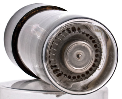
A miniature Dekatron - the GS10C.
Whenever one visits an exhibition of modern electronic equipment, one can almost always see apparatus containing tubes in which a rather fascinating red glow is rotating. The speed of rotation can have any value up to some hundreds per second, at which speed the discharge appears as a circle of red light.
Such tubes are employed in one of the most common types of circuit for counting electrical impulses. The first tubes of this type were designed about 1950 [1] R C Bacon and J R Pollard. 'The Dekatron', Electronic Eng., May 1950.. The tube on the right-hand side of the display indicates the number of units counted, the tube next to it indicates the number of tens, the tube next to that the number of hundreds, and so on. The glow in the units tube rotates at ten times the speed of the glow in the tens tube. Decade tubes divide the number of input pulses by ten so that the output pulses from any tube may (after amplification and phase inversion) be used to operate the succeeding tube. Ten pulses must be fed into the equipment to cause the units tube to make one complete revolution. An output pulse is provided each time the glow in a tube moves from position 9 to position 0.
Counting circuits are known as scalers, since each decade divides or scales down the number of input pulses by a factor of ten. Gas filled decade tubes are often known as 'Dekatrons', but this term is a registered trade mark for the gas filled decade tubes made by Ericsson Telephones Ltd., and should not be applied to tubes of other manufacturers.
Pulse counting equipment is a very important part of modern electronic instrumentation. Apart from its use in radioisotope work, counting circuitry is much used in the automation processes of modern factories for such applications as counting shaft rotations, or for counting the number of articles coming off a production line and automatically placing the desired number in each batch for sale. The pulses need not necessarily be evenly spaced in time.
Some types of gas filled decade tube can count at speeds up to 4 kHz, but a few types are limited to about 1 kHz. Counting tubes of these types are very useful for use with Geiger-Muller tubes for radioisotope work. Faster gas filled decade tubes have also been developed for counting at speeds up to 10 kHz, 20 kHz, 50 kHz, 100 kHz and 1 MHz. They do not all function on the same principle, although certain aspects of the principles of operation of all gas filled decade tubes are very similar. The colour of the discharge is usually red, but some of the higher speed tubes (such as the GC10D and the EZ10B) are filled with a different gas mixture and emit a bluish glow.
High vacuum decade tubes (the E1T and Beam Switching Tubes) are also available, but do not, of course, come within the scope of this article.
Cold Cathodes
In common with all other types of cold cathode tube, gas filled decade tubes have characteristic striking and maintaining voltages. They must always be used in series with a resistive load. They have a very long life when correctly used, but will be quickly damaged by excessive currents. The life of the tubes is prolonged if care is taken to ensure that the discharge does not remain at any one cathode for a period which is longer than a week or so.
Double Pulse Operation
Many tubes operate on the double pulse principle. A double pulse tube consists of a circular anode with thirty rod-shaped electrodes placed around it as shown below.
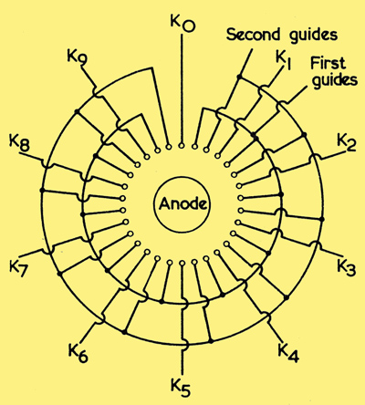
The structure of a double pulse selector tube.
All of the rod-shaped electrodes are identical. Ten are main cathodes and the other twenty are known as guide or transfer electrodes. The guide electrodes serve to transfer the discharge from one main cathode to the succeeding main cathode. They normally receive a positive bias and the discharge will therefore not rest at a guide electrode for any appreciable time, since the anode to main cathode potential is greater than the anode to guide potential.
The ten guide electrodes which are on the clockwise side of the adjacent main cathodes are all connected together and are known as first guides. The guides on the anti-clockwise side of the adjacent main cathodes are also connected together and are known as second guides.
If the glow discharge is resting at the zero position, K0, an input pulse must cause it to be transferred to the next main cathode, K1, for a count to be registered. This involves three separate steps. Initially the input pulse, after suitable amplification and shaping, is applied as a negative-going rectangular pulse to the first guides so that the potential of these guides falls to a value which is well below the earth potential. The discharge therefore moves from the main cathode K0 to the succeeding first guide, since the anode to first guide voltage is greater than the anode to main cathode voltage. It does not move to any other first guide, since only the first guide succeeding the main cathode which is glowing is 'primed' by the ions in the gas formed by the discharge. The ions only travel a short distance in the gas and therefore the priming effect is not very great except between neighbouring cathodes and guides.
When the discharge has rested at the first guide for a short time (about 75 microseconds), a negative-going pulse is applied to the second guides and the first guide pulse terminates shortly afterwards. When the first guide potential returns to its quiescent positive value, the discharge moves to the second guide which is on the clockwise side of the previously glowing first guide. This is the only second guide which is strongly primed. At the end of the pulse the second guides return to their positive bias potential and the discharge moves to the succeeding main cathode which is strongly primed, namely K1. A count has now been registered.
Double pulse tubes derive their name from the two guide pulses which must be applied to them to cause one count to be registered. The two pulses must overlap slightly in time. If the second guide pulse is applied before the first guide pulse, the glow will move in an anti-clockwise direction and the counting will be in reverse (that is, subtraction will take place). Double pulse tubes are symmetrical in each direction and it is only the order in which the pulses are applied to the two sets of guides which determines the direction in which the counting will occur.
In practice the two guide pulses must be derived from a single input pulse. The usual type of circuit which is used to derive the two overlapping pulses from a single input pulse is shown below.
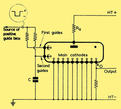
The basic integrator input circuit for double pulse tubes.
The square brackets inside the tube show that there is more than one first guide and more than one second guide, but only one of each is shown for simplicity. When a negative-going pulse is applied to the circuit, the capacitor C maintains the second guide voltage constant for a short time. Similarly at the end of the input pulse C holds the voltage of the second guides constant for a short time. Thus the pulse at the second guides is effectively later in time than the first guide pulse. This simple type of circuit is known as an integrator circuit, since a graph of the second guide voltage against time is (for short times) approximately the waveform which would have been obtained by mathematically integrating the voltage/time waveform applied to the first guides.
Outputs
An output pulse can be obtained from any cathode by inserting a suitable resistor in that cathode circuit. Normally an output is required from the zero cathode of each tube for the operation of the succeeding tube, as shown above. In this case the tube may have all of the main cathodes from 1 to 9 inclusive joined to a common base pin, only the zero cathode having a separate external connection. Such tubes are sometimes known as 'counter' tubes to distinguish them from 'selector' tubes which have each main cathode returned to a separate base pin. An output pulse can be obtained from any main cathode of a selector tube.
The output pulses obtained from gas filled decade tubes are positive-going. These positive-going pulses must be changed in phase before they can operate a succeeding tube. In addition the output pulse voltage is only about 30 Volts and must be amplified to about 120 Volts before it is suitable for the operation of a succeeding tube. Some form of coupling amplifier is therefore required.
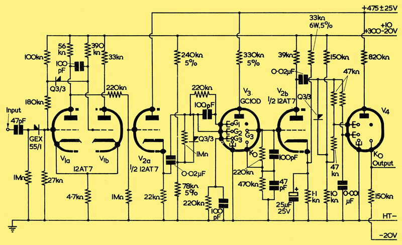
4 kHz Double Pulse Tube Circuit
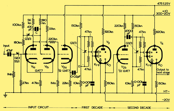
A two-decade circuit for counting at speeds up to 4 kHz. V3 and V4 may be GS10H, GC10B, GC10B/S, GC10/4B, GC12/4B, GS10C/S or GS12D.
A typical circuit designed by the Ericsson Company for use with their double pulse tubes is shown above. This circuit is suitable for the 4 kHz tubes type GC10B, GC10B/S, GC10/4B, GS10C/S, and for the GS10H and 12-way tubes types GS12D and GC12/4B. It will count up to one hundred, but further decades similar to the second decade shown may be added so that the circuit can count up to any desired number.
The input pulses applied to this circuit should be positive-going and have an amplitude of at least 20 Volts. V1(a) and V1(b) form a mono-stable multivibrator. In the quiescent state V1(b) is saturated, since its grid is returned to the HT positive line, whilst V1(a) is cut off by the bias developed by the V1(b) anode current flowing through the common cathode resistor. A positive-going input pulse causes V1(a) to conduct. The anode voltage of V1(a) therefore falls and V1(b) is cut off. The circuit remains in this state whilst the capacitor C is charging through the grid resistor of V1(b). As soon as V1(b)commences to conduct again, the circuit quickly switches itself back to its quiescent state in which V1(a) is cut off. Thus the amplitude and duration of the pulse at the anode of V1(a) are independent of the input pulse characteristics. The GEX55/1 diode in the input circuit prevents the negative trailing edge of the input pulse from reaching V1(a). and causing this tube to be cut off prematurely. The duration of the pulse at the anode of V1(a) can be controlled by choosing an appropriate value of C. In the circuit shown the pulse fed from V1(a) to V2(a) has a duration of about 80 microseconds. The cathode follower stage, V2(a), provides a low impedance output suitable for the operation of the counting tube, V3.
A portion of the pulse from V2(a) is fed to the first guides of V3, whilst the second guide pulse is obtained by means of the normal integrator circuit. The guide bias supply is obtained from the point marked E, at the junction of the 10kΩ and 150kΩ resistors.
The zero cathode of each counter tube is returned to a -20 Volt supply so that larger output pulses can be obtained from the tube. The output pulses are fed to the coupling valve V2(b). This valve is normally cut off by the negative voltage applied to the output cathode, but when the discharge rests at the output cathode, V2(b) conducts. The positive-going pulse from V3 is thus amplified and phase-inverted so that it is suitable for feeding to V4. The capacitor coupling ensures that the pulse applied to V4 does not have an excessive duration even if V2(b) is conducting for a long time.
Ericsson circuits using trigger tubes and also circuits using transistors instead of valves for coupling double pulse tubes have been published. [2] The Ericsson Tube Technical Handbook. (Available on a subscription basis from Ericsson Telephones Ltd., Beeston, Nottingham.) Mullard circuits for driving their tubes from valves, [3] G F Jeynes. 'Decade Stepping Tubes and Their Operation'. Mullard Technical Communications, Vol. 4, No. 37 (February 1959). (Also reprinted as a separate booklet of the same title.) [4] 'Stepping Tubes', Mullard Outlook, March 1959. trigger tubes [5] G F Jeynes and S Zilkha. 'Trigger,Tube Coupling Circuits for Counting Tubes'. Mullard Technical Communications, Vol. 7, No. 64, p. 184 (August 1963). [6] G F Jeynes and S Zilkha. 'Cold Cathode Trigger Tube Coupling Circuits for the Z504S Stepping Tube'. Mullard Applications Lab. Report, ARL594., and transistors [7] G C Chappell and G F Jeynes. 'Transistorised Coupling Circuits for the Z504S Stepping Tube'. Mullard Applications Lab. Report, ARL6l2. are also available. American manufacturers have designed rather different types of circuits [8] Sylvania Counter Tube Handbook. [9] 'Operation of Decade Counter Tubes'. Raytheon Publication No. SPIO97 (1963)..
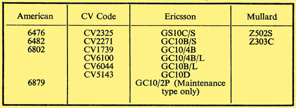
Counter Tube Equivalents and Near Equivalents.
Asymmetrical Tubes
Double pulse tubes are symmetrical with respect to the clockwise and anti-clockwise directions, but two guide electrodes are required between each two main cathodes to ensure that counting occurs only in the desired direction. Other types of tube are available in which the direction of counting is determined by the asymmetrical structure of either the guide electrodes or of the main cathodes or both. Such tubes employ only one set of guide electrodes. Examples are the Elesta EZ10B [10] 'Die Ziihlrohre EZIOB in Transistorschaltungen'. Elesta Techrlzisgite Mitteilungen, Nr. 18, April 9. and the STC G10/241E 'Nomotron' [11] 'G10/241E Nomotron'. STC Valve Division Application Report, No. MS/114..
If the discharge is resting at the zero cathode of one of these tubes, an input pulse applied to all of the guide electrodes will cause the discharge to move to the guide following the zero main cathode. At the end of the input pulse the discharge moves to the main cathode following the zero cathode, since the guides receive a positive bias. The shape of the guides and/or of the main cathodes ensures that the discharge can move only in a clock-wise direction. These tubes cannot be used to count in the reverse direction.
The GC10D Tube
Another type of tube is the Ericsson single pulse Dekatron type GC10D. The construction of the GC10D is similar to that of the double pulse tube shown in the first diagram, but forty electrodes are employed around the central anode instead of thirty. Ten of the electrodes are main cathodes whilst the remaining thirty are first, second and third guide electrodes. There are three guide electrodes between each two main cathodes. All of the first guides are joined together and are brought out to a common base pin. Similarly all of the second guides are brought out to one external connection. The third guide preceding the zero cathode is connected to its own base pin, whilst the remaining third guides are connected to a common base pin.
A GC10D 20 kHz circuit with coupling to a succeeding 4 kHz tube (V4).
The GC10D can be used in the type of circuit shown above for counting at frequencies up to 20 kHz [12] J R Acton. 'The Single Pulse Dekatron'. Electronic Eng., February I952.. Normally a GC10D tube is only employed in the first decade, since a slower and slightly cheaper 4 kHz tube is perfectly satisfactory for use in the second decade. The input circuit is very similar to that of the earlier circuit, but the capacitor which is connected between the anodes of V1(a) and V1(b) has been reduced in value from 470pF to 100pF so that the pulses provided by the input circuit are shorter. The GC10D can operate with input pulses of about 25 microseconds duration.
The input pulses are applied simultaneously to the first and second guides of the GC10D (V3). The discharge moves first to the primed first guide, but when the anode current flows through the first guide resistor, the first guide potential is raised and the discharge quickly steps to the second guide. At the end of the input pulse, the discharge moves to the third guide, but the current flowing through the third guide resistor causes the third guide potential to be increased until the discharge moves to the succeeding main cathode.
If the third guide preceding the zero main cathode were connected directly to earth, the discharge might step back from the main cathode to this guide when the main cathode became positive due to the flow of the tube current through the zero main cathode resistor. The third guide preceding the zero main cathode (shown on the right of the tube symbol) is therefore returned through a 220kΩ resistor to the zero main cathode. This ensures that as the main cathode potential increases when the anode current flows through the cathode resistor, the third guide potential will also increase so that the glow will not step back to this third guide.
The output pulses from the coupling tube, V2(b), in the circuit above are used to operate a normal 4 kHz decade tube. Any further decades which may be required may be similar to the second decade shown in the earlier circuit.
Although there are four separate stepping movements of the discharge in the operation of the GC10D, two of these occur automatically. The overall operating speed can therefore be greater than that of the simple double pulse tubes in which three stepping operations occur for each pulse which is counted. Double pulse tubes are available for operation at 10 kHz, 50 kHz and 100 kHz; the input pulses fed to these tubes have a shorter duration than those required by 4 kHz tubes.
The Use of Decade Tubes With E-M Counters
The electro-magnetic counter [13] J B Dance 'Electro-magnetic Counters' The Radio Constructor, October 1963, p. 190. can normally count at speeds not exceeding about 25 pulses per second, but has the advantage that one small, compact and reasonably cheap unit can indicate up to at least six digits. Each decade tube can only indicate a single digit. If it is required to count pulses at frequencies up to 1 kHz, it is common practice to employ two cascaded tubes followed by an electro-magnetic counter. The decade tubes each divide the pulse rate by ten, so that the electro-magnetic counter will not be required to count at a speed greater than ten counts per second. This method is more economical than if decade tubes alone are employed to display six or eight figure counts.
The output pulses from the decade tube do not have nearly enough power for them to be able to operate an electro-magnetic counter directly. In addition their duration is not usually suitable.
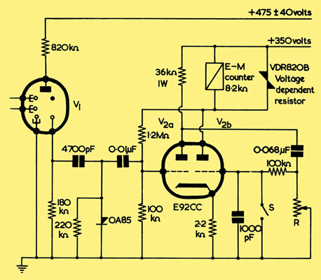
Using a decade tube to drive an electro-magnetic counter. V1 is a 4 kHz Dekatron.
A circuit such as that shown may be used to amplify and shape the pulses so that they are suitable for the operation of an electro-magnetic counter [14] 'Dekatron-Tube Circuit for Reducing the Frequency of Impulses for Operating TCe Counters'. Sodeco Information Sheet E48..
The input circuit which operates the decade tube, V1, may be similar to that of the two decade circuit presented earlier. The positive-going output pulses from V1 of the circuit above are short-circuited to earth by the OA85 diode. The negative going trailing edges are used to trigger the monostable multivibrator circuit of V2 which shapes the pulses into a form suitable for the operation of the electro-magnetic counter in the anode circuit of V2(b). The voltage dependent resistor, VDR820B, short-circuits any voltage peaks which are developed as the current in the coil of the counter is cut off.
The value of R can be adjusted until each pulse has the desired duration. If the value of R is 120kΩ, the duration of the pulses of current through the coil of the electro-magnetic counter will be about 20 milliseconds.
Reset
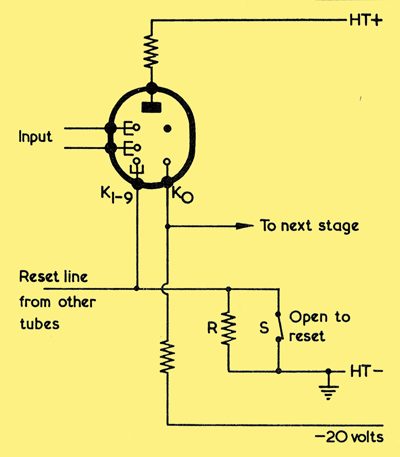
A circuit which enables the tubes to be reset to zero.
In most circuits it is desirable to be able to reset the decade tubes to zero. This can be carried out in the circuits presenter here by returning the cathodes 1 to 9 of all tubes to a common negative reset line separate from the earth line. This negative line is connected to earth via a resistor (R) which is normally short-circuited by a switch. During the resetting operation the switch is opened so that all of the main cathodes except the zero cathodes rise in potential.
The glow in each tube therefore moves to the zero cathode. The value of the resistor joining the common return line to earth varies with the number of decade tubes employed, but should be chosen so that the cathodes (other than the zero cathodes) of the decade tubes rise in potential by about 100 Volts during the resetting operation.
The switch S in the Electro-mechanical circuit must be closed during the resetting operation to prevent a spurious pulse being recorded by the electro-magnetic counter. Normally this is carried out by contacts on the relay or switch which is used for reset. The switch S should open after the decade tube resetting contacts have returned to their normal position.
Accurate Timing
Decade tubes are often useful when an operation must be accurately timed. For example, in welding operations it is often required to apply the power for a certain time and decade tubes can be used for this purpose [15] T W Brady. 'The Use of Cold Cathode Counting Tubes for the Control of Resistance Welding'. Electronic Eng., February 1956. [16] G F Jeynes and M Veeraju. 'Synchronous Resistance Welder Controller for 1 to 130 cycles'. Mullard Technical Communications, Vol. 6, No. 54, p. 172.. They may also be used to provide small marks on an oscilloscope screen which correspond to very short time intervals [17] J H L McAuslan. 'A Dekatron CRO Time Marker'. Electronic Eng., December 1952.. Thus the X axis is calibrated in time units directly.
In many Geiger counting systems it is desirable to have an automatic timer which will stop the counting decade tubes so that the second decade tube provides one output pulse per second. If another three decade tubes are added, the final tube will provide one pulse each thousand seconds. This pulse may be used to cut off a valve and stop the counting process in a separate counting circuit.
Alternatively a scale of twelve tubes combined with a decade tube used as a scale of five may be used to divide the 1 Hz pulses by 60 in order to obtain 1 pulse per minute. Circuits have been published which enable decade tubes to divide the incoming pulse rate by any number up to nine [9] 'Operation of Decade Counter Tubes'. Raytheon Publication No. SPIO97 (1963)..
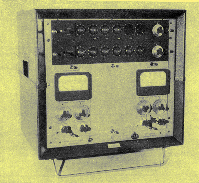
The Ekco automatic scaler type N610A for nucleonic work. The upper row of tubes performs the counting operation on the input pulses, whilst the lower row performs the automatic timing operations which enable the scaler to switch itself off after a pre-set time. The two tubes on the top right hand side of this scaler are not counting tubes; they are tubes for indicating the state of the count in two high speed valve counting circuits. (Ekco Electronics Ltd).
References
- R C Bacon and J R Pollard. 'The Dekatron', Electronic Eng., May 1950.
- The Ericsson Tube Technical Handbook. (Available on a subscription basis from Ericsson Telephones Ltd., Beeston, Nottingham.)
- G F Jeynes. 'Decade Stepping Tubes and Their Operation'. Mullard Technical Communications, Vol. 4, No. 37 (February 1959). (Also reprinted as a separate booklet of the same title.)
- 'Stepping Tubes', Mullard Outlook, March 1959.
- G F Jeynes and S Zilkha. 'Trigger,Tube Coupling Circuits for Counting Tubes'. Mullard Technical Communications, Vol. 7, No. 64, p. 184 (August 1963).
- G F Jeynes and S Zilkha. 'Cold Cathode Trigger Tube Coupling Circuits for the Z504S Stepping Tube'. Mullard Applications Lab. Report, ARL594.
- G C Chappell and G F Jeynes. 'Transistorised Coupling Circuits for the Z504S Stepping Tube'. Mullard Applications Lab. Report, ARL6l2.
- Sylvania Counter Tube Handbook.
- 'Operation of Decade Counter Tubes'. Raytheon Publication No. SPIO97 (1963).
- 'Die Ziihlrohre EZIOB in Transistorschaltungen'. Elesta Techrlzisgite Mitteilungen, Nr. 18, April 9.
- 'G10/241E Nomotron'. STC Valve Division Application Report, No. MS/114.
- J R Acton. 'The Single Pulse Dekatton'. Electronic Eng., February I952.
- J B Dance 'Electro-magnetic Counters' The Radio Constructor, October 1963, p. 190.
- 'Dekatron-Tube Circuit for Reducing the Frequency of Impulses for Operating TCe Counters'. Sodeco Information Sheet E48.
- T W Brady. 'The Use of Cold Cathode Counting Tubes for the Control of Resistance Welding'. Electronic Eng., February 1956.
- G F Jeynes and M Veeraju. 'Synchronous Resistance Welder Controller for 1 to 130 cycles'. Mullard Technical Communications, Vol. 6, No. 54, p. 172.
- J H L McAuslan. 'A Dekatron CRO Time Marker'. Electronic Eng., December 1952.
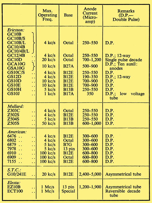
Table of Gas Filled Counting Tubes.
|