|
The factors contributing to the noise in electronic equipment can be gathered together and expressed as resistances connected in the input circuit of an otherwise noiseless receiver.
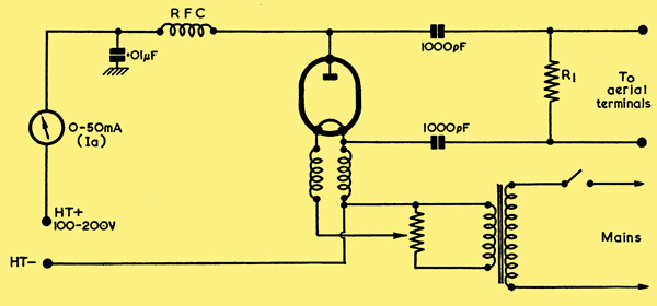
Circuit of the noise generator
Lumping together of the effective noise generating elements is both helpful in explaining their individual contribution to the total noise, and also of assistance in calculating the noise level in the set. However, such a calculation is not easy to make accurately, as many of the factors which govern it are not easily determined, and the more usual method of finding the noise level is by measurement. This measurement is usually made by comparing the noise level in the receiver under test with that of a known source in a manner which will be described later.
The formula for calculation of the noise generated by a thermionic valve is:-
Noise current i = √(2e Ia B K2)
Where e = 1.59 x 10⁻¹⁹, B = bandwidth in Hz and K is a constant.
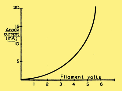
The constant K depends upon the proportion of the electrons leaving the cathode which arrive at the anode. This property of a valve for producing noise is utilised in the noise generator which incorporates a thermionic diode. In order that there should be no doubt as to the value of K in the noise diode it is operated in saturation, a condition where every electron leaving the cathode arrives at the anode, thus K = 1. These special diodes usually have a fine tungsten filament which is fed from an adjustable voltage source so that the electron emission may be varied to vary the noise output. The valve is maintained in saturation by an anode voltage which is in the region of 200 V. The complete circuit of the noise generator is simple and is shown above. The graph below shows the manner in which the anode current of the diode varies in accordance with filament voltage, assuming an anode potential which is sufficiently high to maintain the valve in saturation. The noise is distributed over a wide bandwidth, which is usually limited first by the capacity shunting effect of the diode itself. A noise range which conforms exactly to the formula quoted can, however, usually be relied upon up to 100 MHz. Whilst special noise diodes are available from valve manufacturers, experimenters may like to use the ex-Government type CV172 which is available on the surplus market.
To use the noise generator, the output resistance R1 is made equal to the input matching resistance of the receiver, usually 50 Ohms, and the unit connected across the aerial terminals. A device is required to indicate the relative noise levels in the set, and for this purpose an AC voltmeter capable of recording millivolts is required; a normal low reading voltmeter with an amplifier is quite suitable.
Making a Measurement
Before attempting to make a measurement, the set under test must be installed under normal working conditions at which the measurement is to be taken. It is important that the RF and IF stages are correctly aligned as it has already been shown that the overall bandwidth has a considerable effect upon the noise level. The output level indicator is connected to the output of the last IF stage, and the noise generator across the aerial terminals. The receiver and indicator are then switched on and allowed to warm up, and at this stage the filament voltage of the noise diode is set to zero. When the receiver reaches working temperature there will be a reading on the indicator which is proportional to the total noise generated by the RF and IF stages. The gain of the amplifier in the indicator should be adjusted until the meter reads about a quarter of full scale. A quick check is desirable at this stage to ensure that the meter is in fact reading noise and not being disturbed by a signal picked upon the wiring.
The filament voltage of the diode is now gradually increased until the noise power shown by the meter is doubled. As the meter is recording voltage an increase in power of 2:1 is shown by an increase in voltage of √2 or 1.4 times. Thus the filament voltage of the diode is adjusted until the meter reads 1.4 times its original value. Under this condition the noise fed into the receiver from the generator is exactly equal to the noise occurring within the set itself. At this stage the anode current of the noise diode is noted, and its value may be used to calculate the noise current which is flowing in the matching resistor R1.
Noise Factor
It is, however, better practice to quote the noise performance of a receiver by stating its 'Noise Factor'. This term has been given to the ratio of the noise power applied to the receiver from the generator to the noise power available from the aerial resistance. Using the formulae already given it may be shown that the noise factor may be calculated by:-
NF = 20 Ia R1
where Ia is the anode current of the noise diode in amperes and R1 is the aerial resistance, which in the example under consideration is 50 ohms.
Construction of Generator
For readers who are interested in the actual measurement of noise, a few comments regarding the construction of the generator may be helpful. The noise generator should be housed in a small metal container and the output leads kept as short as possible. The choke in the anode circuit is a good all-wave component, whilst the heater chokes may consist of 30 turns of PVC covered wire wound into a self-supporting coil with the aid of a pencil used as a mandrel. The filament voltage is adjustable from zero to the maximum permitted for the diode employed, 7 V in the case of the CV172. This control is obtained by means of a wire-wound potentiometer connected across a 7 V filament winding on a mains transformer. The HT supply voltage is not critical and may be between 100 and 200 V, and this can be obtained from a simple half-wave rectifier circuit with an R-C smoothing filter. It is seen that the noise generated is dependent upon the diode anode current and the resistor R1 which is made to equal the aerial input resistance of the set being tested. Thus for a given value of R1 the anode current meter may be calibrated directly to read noise factor.
|