|
The Cathode-Ray Tube is used in instrumentation and picture presentation. In this 1955 article the CRT is discussed with specific application to the oscilloscope.
Objects
The purpose of the oscilloscope is to draw what is virtually a graph of regularly varying electrical quantities, such as voltage or current, against a horizontal scale of time. If, for example, we were to connect our oscilloscope to a point in a circuit where a sinusoidal signal existed, a picture of the sinusoid should appear on the screen of the oscilloscope. If the frequency of the signal were 25 Hz, and the horizontal scale were 0.5 second, 12.5 cycles would be displayed. The vertical axis would normally represent voltage.
The Cathode-Ray Tube
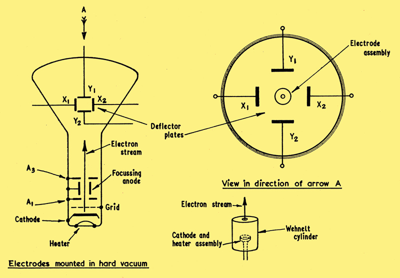
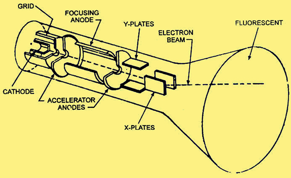
The heart of the oscilloscope is the cathode ray tube. This is the device which produces the picture, and therefore all the circuitry is designed around it. The left hand diagram above shows an electrostatically deflected tube.
At the base of the tube there is a cathode heated in the same way as in an ordinary valve. This cathode therefore emits electrons, which are attracted away from it by the anode A1. Between the cathode and the anode there is a 'grid' consisting of a tube with a hole in one end, as shown above right. This is called the Wehnelt cylinder. By biasing this electrode relative to the cathode, a variation in the number of electrons passing through the hole may be achieved, as in the case of a normal valve. Beyond this electrode is an anode positively charged with respect to cathode. This anode is often in the form of a disc with a small hole at its centre. The electrons are attracted toward this electrode and stream through the hole at the centre. One or two further anodes may be situated beyond the first anode. These are of essentially the same mechanical form as the first anode, but they are connected to progressively higher potentials.
By the time the electrons have passed through these anodes, they are concentrated into a narrow beam. The potential of the second anode is normally made variable, so that focusing of the electrons into the narrowest possible beam may be achieved. The second anode is, therefore, called the 'focusing anode'.
The thin pencil beam of electrons is travelling at a high velocity when it leaves the final anode, and is therefore capable of traversing the space between the final anode and the screen. The inside face of the screen is covered with a material which fluoresces when the electrons strike it. A small spot of light, therefore, appears on the screen. The intensity of the light is controlled by varying the grid voltage as previously mentioned. So much for the production of the spot - now lets see how it may be moved around the screen.
Deflection
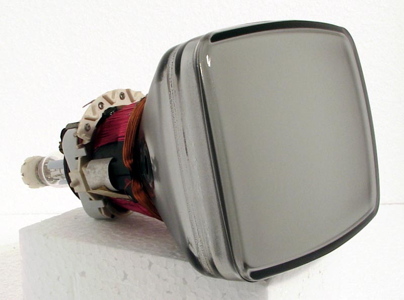
A small magnetically deflected CRT of the type found in the 1980's for portable monitors
There are two main methods of deflecting the spot: (a) Magnetic and (b) Electrostatic.
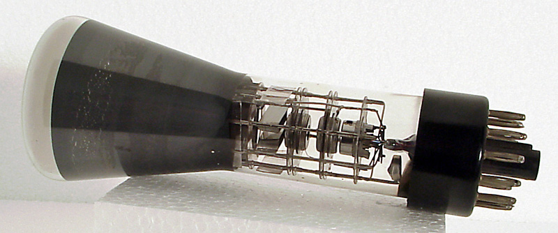
A small oscilloscope CRT of the type used in 1955 when this article was written
Magnetic deflection is seldom used in oscilloscopes, but is almost invariably used in television receivers. As we are concerned with oscilloscopes here, magnetic deflection will be dealt with very briefly. It is worth noting that the focusing system described above is electrostatic, that is, it is controlled by the potential of the second anode. Focusing may be achieved magnetically, if required, and is frequently used in TV receivers.
The operation of magnetic deflection is quite simple. If a magnetic field is brought near to the electron beam after it has left the final anode, the beam will bend. This deflection of the beam from the straight path it was originally following causes the spot to take up a new position on the screen, because the electrons strike the screen at a different point. Variation of this field will, therefore, vary the position of the spot on the screen. To achieve this, coils are placed outside the tube envelope, and a current passed through them. Variation of this current will change the field, and so deflect the spot.
Electrostatic deflection is, however, achieved by means normally contained within the tube. Returning to the left hand diagram above for a moment, we see that two sets of flat plates are placed either side of the electron beam. The set which will deflect the beam horizontally are called the X plates, and those deflecting in a vertical direction the Y plates. This follows the convention for naming graph axis.
The method by which deflection is achieved is similar to the magnetic case. If a positive potential is applied to one of the plates, the electrons will be attracted toward it, that is, the beam will be deflected. The spot will, therefore, take up a different position on the fluorescent screen. If a negative potential is applied, the electrons will be repelled by the plate and the beam will be deflected in the opposite direction. If, therefore, a regularly varying voltage were applied to one of the plates, the spot would move backward and forward across the face of the tube. If the rate of movement were sufficiently rapid (i.e. the frequency of the applied voltage were high enough), the eye would be fooled into believing that a continuous straight line were being drawn across the tube.
Clearly, then, the application of the appropriate voltages to the deflector plates enables us to move the spot to any position on the screen. As usual, however, there are one or two limitations to the cathode ray tube which make life difficult for the user.
Distortion
From the simple explanation of cathode ray tube operation given above, one would expect the spot to remain the same size at whatever position it occupied on the tube face, because focusing of the electron beam was carried out well before the deflector plates were reached. However, it has been found that the application of deflection voltages to the plates brings about de-focusing of the beam. The effect worsens as the spot moves further from the centre of the screen. This may be overcome by what is called 'symmetrical deflection'. This merely means that if 10V positive have to be applied to one plate to move the spot a certain distance, then +5V on one X plate, say, and -5V on the other X plate would produce the same deflection but with less deflection de-focusing. For example, a push-pull amplifier might be used, with the anode connected to a pair of X or Y plates.
Another form of distortion is astigmatism. This means that focus may be obtained in, say, the vertical or Y direction, but not in the horizontal or X direction. Tubes are usually internally corrected for this defect to a certain degree, but circuitry can be devised to minimise it even further.
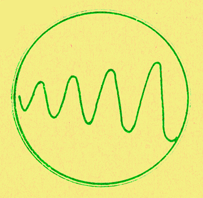
Trapezium distortion which results in a rectangular picture on the tube becoming a trapezium is virtually absent in many modern tubes, but the effect is illustrated below, where a sine wave of constant amplitude appears to grow in amplitude at one end of the trace.
So much for the tube itself. The most important thing to discover now is how to operate it.
Power Supplies
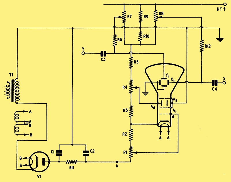
Above can be seen a typical power supply for a cathode ray tube. For a practical circuit with component values see here. T1 is the mains transformer and V1 a high voltage rectifier such as the Cossor SU2150A. The transformer must produce 1kV to 5kV, depending upon the tube used. We will assume an average tube working at 2.5 kV. C1, C2 and R11 form a ripple filter, the output side of which is 2.5kV negative with respect to earth. The CRT operating potentials are derived from the chain of resistors, R1 to R5.
The cathode is connected to a point some 40 or 50 volts positive from the point A, and the grid is returned to the slider of R1, which varies the potential of the grid relative to cathode. This, therefore, is the brilliance control. In practical circuits, A1 and A3 are connected together as shown. A2, the focusing anode, is connected to the slider of R4. This electrode is nominally at about ±200 V from the point A, but sufficient variation is allowed by the use of R4 to achieve optimum focusing. A1 and A3 are connected to earth.
Deflector plates Y1 and X1 are connected to the 'shift' potentiometers R7 and R8. These vary the potentials of the plates positive or negative with respect to A1 and A3. The spot may be placed, therefore, at any convenient position on the face of the tube. When, for example, R7 and R8 are half way along their tracks, the potentials of X1 and Y1 will be the same as that of A1 and A3, and the spot will be central. This assumes that R9 and R10 are equal in value, which would normally be the case. Y2 and X2 plates are shown connected directly to earth.
R6 and R12 are the deflector plate leaks. If a signal, let us say, a sinusoid, is applied to C3, the signal will swing symmetrically either side of the voltage at which R7 is set. The spot will be disturbed, therefore, either side of its set position, in the Y direction. A line of light will, therefore, appear vertically on the face of the tube.
The question now arises, what is the use of applying a sine wave to the tube when it merely draws a straight line? Surely one would expect to see the picture of a sine wave. Quite true . . . And the mechanism by which this is obtained is to apply a linearly changing voltage to the X plates. This forms a 'timebase'.
Sweeping
Suppose for a moment that the sine wave applied to the Y plates were of a low frequency, just a few cycles per second. At the same time, the X shift potentiometer is rotated at a regular rate, so that the spot is deflected smoothly from the left hand side of the tube to the right. The spot would now fall under two influences. It would be moving up and down sinusoidally and linearly from left to right.
It is easy to simulate this effect. Place a sheet of paper on a table, and move a pencil in a straight line backward and forward on the paper, while someone is moving the paper smoothly away in a direction at right angles to the pencil movement. A very rough sine wave will result.
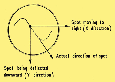
The diagram above shows the effect on the CRT. When the spot reaches the right hand side of the tube, one picture is complete, and it must be returned very rapidly to the left in order to start another picture.
If we graph the voltage applied to the X plates during this operation, we will obtain the shape below. This is called a 'saw-tooth_wave-form'.

X plate waveform to deflect the spot to produce the trace shown above
This waveform must be produced regularly and at a frequency equal to, or an integral (i.e. whole number) number of times slower than, the applied frequency. If, for example, our sinusoidal signal on the Y plate had been at 50Hz, then the saw tooth must run at 50Hz, or 25Hz, or 16.6Hz, etc. If it ran at 50Hz, one sine wave would appear, if at 25Hz two sine waves, at 16.60Hz, three sine waves, and so on.
Obviously, it would be inconvenient, not to say impossible, to waggle the shift potentiometer about at these speeds, so we have to resort to more subtle means. These means open up a vast field of circuitry. The basic device for producing the 'sawtooth' is called a timebase, and may take many and varied forms.
This article predates post deflection acceleration and tubes had limited brightness as higher EHT reduced deflection sensitivity. With PDA the first anodes operated at modest voltages and relatively low energy electrons were deflected. After deflection the electrons entering the bell of the tube would encounter a much higher EHT voltage that was applied to a graphite coating inside the bell. Oscilloscope tubes could operate with eight to 14 kV on the PDA electrode.
|