|
The Evolution of the Ultra-short Wave.
The congestion of the ether is becoming so great that efforts are continually being made to extend the channels of communication to higher frequencies. Wavelengths as low as 12 metres are now commonplace, but attempts to work below this are fraught with many difficulties. At about one metre the period of oscillation is comparable with the time that the electrons take to pass from electrode to electrode in the valve, and the ordinary valve-oscillator theory breaks down. The accompanying article outlines the history of short-wave communication and summarises the position today.
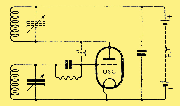
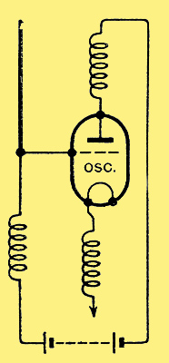
The fundamental oscillator circuit. If grid and anode circuits are in resonance the electrostatic coupling produced by the valve's electrode capacity is sufficient to cause oscillation.
Since the War (1914-18), on account of the increasing congestion in the field of radio communication, attempts have been made to extend in every possible direction the range of frequencies available for this purpose.
At the close of the War the generally used wavelengths ranged between 100 and 20,000 metres (3,000 to 15 kHz), Since the 10-15 kHz range verges upon the audio frequency spectrum, there was obviously no room there for extension, so wavelengths had perforce to be found in the zone below 100 metres (above 3,000 kHz). How the use of wavelengths below 100 metres and down to 15 metres was developed is now a matter of fairly common knowledge.
Of course, there was one great advantage in the possibility of using ultra-short waves, apart from the relatively efficient aerial systems which could be used in connection with them, i.e., the fact that stations could be packed closer (since the spacing was a matter of frequency difference) as the wavelength was reduced. Even so, the waveband between 15 and 100 metres soon became congested, and so the possibility of using even shorter waves was soon investigated.
Though it is not really within the province of this article, it may be profitable to discuss briefly the properties of these very short waves. As predicted by theory, it was very soon discovered that they were too short to be reflected or refracted by the ionosphere, and therefore there was no phenomenon of skip distance, due to the presence of the direct and indirect rays. Also the ground wave suffered very rapid attenuation, so that sending or receiving apparatus situated close to the ground had a very short range. In fact, the range bore a direct relationship to the height of the antenna from the ground. If, however, the two stations were situated so as to be within sight of each other, very long ranges were obtained with very small powers. The waves behaved in this way in a very similar manner to the much shorter light waves, themselves the name quasi-optical.
Very early during the pioneer work on these waves in the field of communication it was suggested that it would be possible to control the service area of a transmitter by altering the effective height of the antenna. The use of directive aerial systems was also easy and economical.
But some workers in this particular branch of radio communication have long felt that, in spite of theory and early results, it might be possible to attain long ranges with these waves. Some recent experiments have tended to confirm this view, ranges well beyond the optical range having been attained, first between France and Corsica on wavelengths of the order of 3 metres, and lately between ship and shore over a distance of 168 miles on a wavelength of 57 centimetres announced at a recent talk before the Royal Institution given by Marchese Marconi. The mechanism of propagation in these cases is not yet understood.
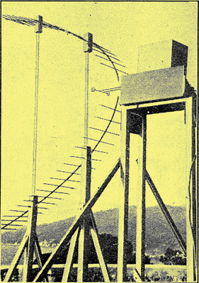
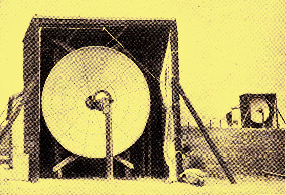
A receiver for the quasi-optical wavelength of 50 centimetres recently used by Marchese Marconi.
Prior to this time, methods of generating very short waves had been sporadically used, mostly for physical research purposes. The basis of nearly all successful methods is, of course, the triode, in one form or another.
There are two forms of circuit suitable for the generation of very short waves by means of the triode valve: First, the reaction circuit, and, secondly, the electron-oscillation circuit. With care, the reaction type of circuit may be used to generate wavelengths down to 1 metre in length, but the power available and the efficiency falls off rapidly below 2 metres. This is because the period of oscillation (1/f) is comparable with the time of transit of the electrons within the valve, so that it becomes impossible to ensure that there shall be the correct phase relationship between the electrode voltages and currents according to standard. valve-oscillator theory to give normal efficiency.
To generate wavelengths shorter than a metre in length, use must be made of the natural period of flight of the electrons between the valve electrodes. This is the basis of the electron-oscillation methods of generating very short waves, due in the first place to Barkhausen, Kurz, Gill, and Morrell See B-K mode. By these means waves as short as 5 centimetres have been successfully generated and controlled.
Oscillation systems
The application of reaction methods of producing ultra-short waves is very interesting in its development, and throws light upon the question of valve oscillator circuits in general.
Consider the fundamental oscillator circuit shown at the top of the page. The coupling between the grid and anode circuits may be either by means of the interlinking magnetic fields of the two coils, the inter-electrode capacity (grid-anode) of the valve, or a combination of both. Whether this coupling is sufficient to produce oscillation will depend, among other things, upon how close to mutual resonance the two circuits are. If they are in resonance, the slightest magnetic coupling, or the small amount of electrostatic coupling represented by the inter-electrode capacity of the valve is amply sufficient to produce oscillation. Hence the tuned anode-tuned grid type of oscillator favoured by amateur short-wave transmitters. The circuit above may be redrawn as below.
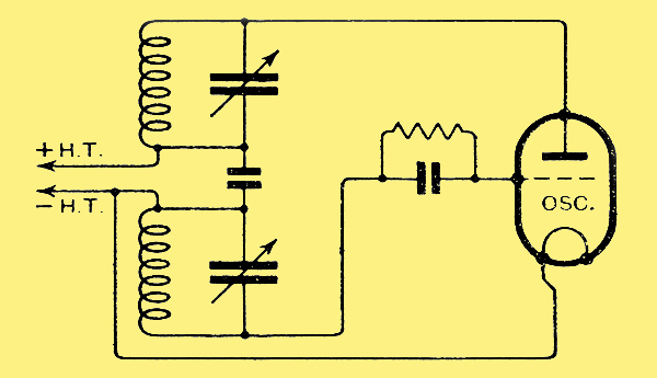
The basic oscillator circuit redrawn without the HT Battery.
Since the source of HT contributes nothing to the sum of the HF potentials, we have omitted drawing it in. The two coils and tuning capacitors are seen to be virtually in series, so an obvious simplification is as shown below, producing the well known Hartley circuit, either series (a) or shunt fed (b).
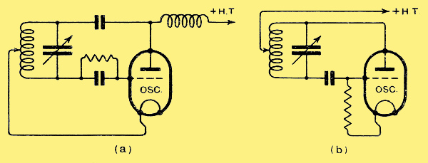
A simplification producing the well-known Hartley circuit with (a) series and (b) shunt feed.
Any of the types of oscillator just described may be used with success on ordinary short wavelengths (down to 5 metres), but when we wish to generate shorter waves still they are not so satisfactory. Using an ordinary large receiving valve or small transmitting valve, the lengths of the leads within the valve may be quite as great as the length of wire forming the coil, so that, instead of having a true Hartley circuit as above, we have the queer arrangement shown below.
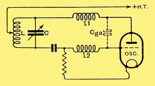
An oscillator for a wavelength of about four metres.
This leads to several troubles. First, the relative amount of inductance included between the capacitor terminals is small compared with the total amount ot inductance in the circuit, the parts of the inductance lying without the L-C circuit acting as chokes and reducing the potentials applied to the valve electrodes. Secondly, we can trace two coupled circuits in the above diagram, one being the L-C circuit, and the other the circuit via L-l1-Cga-l2. Under these conditions, when C is reduced below a certain point, it loses control, and the second of the two circuits, that via the inter-electrode capacity (Cga) of the valve takes charge, and the generated wavelength suddenly jumps to some value quite unrelated to the setting of the tuning capacitor C. The combination of these effects sets a limit (round about 4 metres, usually) to the shortness of the wavelength generated by this type of circuit. It had also two further disadvantages. First, if it was shunt fed (b), part of the self-capacity of the choke used to introduce the anode feed was added to the other effective stray capacities in the circuit, since it was connected at a point of high HF potential; if series fed (a), there was the damping effect of the grid leak (generally quite low in ohmic resistance, not more than 20,000 ohms) and the capacity of the grid capacitor to earth, the grid capacitor, in these very short-wave circuits, being a relatively bulky component. Secondly, in either case both sets of vanes of the tuning capacitor are at a high HF potential relative to earth.
A Push-Pull Circuit
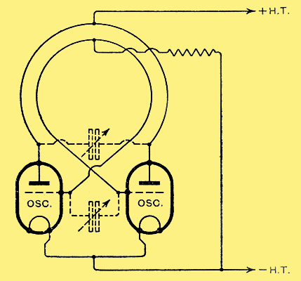
The Mesny push-pull oscillator successfully employed for wavelengths down to about three metres.
To overcome most of these disadvantages, the push-pull circuit shown above and generally ascribed to R Mesny was used. Here the valve inter-electrode capacities are effectively in series as regards the tuned circuit, and a high degree of electrical symmetry, which is very desirable, is attained. But the latter objection urged against the Hartley circuit still exists. Also, on account of the fact that only half of the tuned circuit is effective as a load in the anode of each valve, the effective anode load decreases much more rapidly with a decrease of wavelength than in the case of the single-valve circuit, though this is partly offset by the smaller effective inter-electrode capacities.
The Mesny type of circuit is usually successful down to about 3 metres with ordinary valves. Note that the effective reaction coupling in this case is partly electromagnetic. If the coils are constructed the wrong way round (uncrossed), the two reaction effects (electromagnetic, via the coils, and electrostatic, via the valve inter-electrode capacities) may cancel out and no oscillations be obtained. A suitable single-valve circuit, apart from avoiding the necessity of pairs of matched valves, can, if properly designed, be made to operate at shorter wavelengths than the Mesny type of circuit. The forerunner of the most successful type of single-valve circuit for this purpose seems to have been devised by Messrs. Gutton and Touly round about the year 1919, and is shown below.
An early single-valve short-wave circuit of symmetrical form.
One comment upon it is necessary: the mistake was made of having the grid capacitor in the position shown, where it is (to use an illuminating expression that the writer once heard) knocked about at a high-frequency potential above earth. A later version of the circuit is shown below.
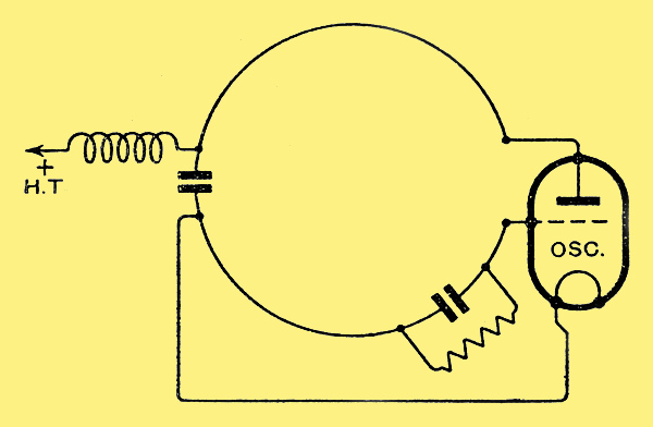
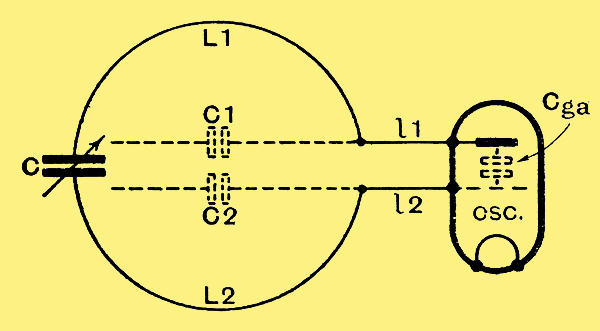
A later version of the circuit shown above.
When we examine it closely we find that it is hard to describe it in terms of conventional valve circuits. The beauty of this arrangement lies in the fact that the external inductances L1, L2 are continuous with the internal leads l1, l2, the whole tuned circuit being formed by the two inductances L1-lI, L2-l2 and the two capacities C and Cga, forming a link. if carefully arranged, this circuit is much less likely to show the undesirable coupled circuits effect of the Hartley circuit previously described. Furthermore, there is no limit to the shortness of the external leads (L1, L2) beyond that of the length necessary for mechanical reasons, to connect C. Moreover, the grid and anode current leads can be led in (as shown via chokes) at points of low or zero HF potential with regard to earth.
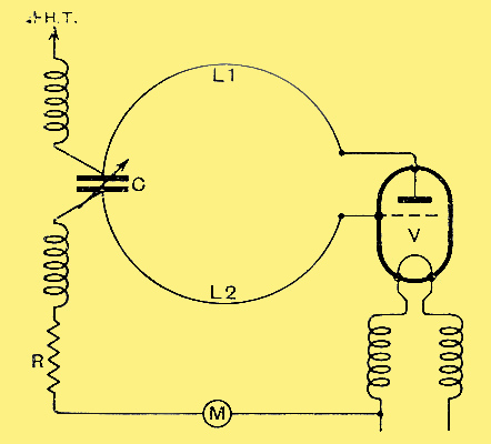
The equivalent circuit of the last diagram with the self-capacities shown.
Practically, the circuit values for this circuit may be: V-any receiving power or super-power valve; Ra about 2,000-4,000 Ohms; L1 and L2, pieces of stout copper wire, bent into semicircles, each piece about 4 inches long; C, any good make of air-dielectric miniature variable capacitor, about 0.0001 μF max.; and R, 10,000-20,000 Ohms.
Thegrid and anode chokes may each consist of about fifty turns of fine wire on a former 3/8 inch diameter. Filament chokes will usually be found necessary and may consist of the same number of turns (fifty) of stouter wire (say, 30 SWG, for a valve taking not more than 0.25 Amp. filament current) wound in bifilar fashion on a former about 3/4 inch diameter
With the arrangement described, the wavelength obtained will be somewhere in the neighbourhood of 2.25 metres. This circuit has the great advantage that it never refuses to oscillate, provided that the valve is OK. By decapping the valve, cutting the external leads as short as possible, carefully adjusting the value of R (the grid leak), using a selected valve, and applying as much anode voltage as it will stand safely, the generated wavelength (with C at its minimum value consistent with oscillation) may be brought down to the neighbourhood of 1.5 metres.
A close inspection of the diagram immediately above will show that if the self-capacities between the various parts are considerable (especially in the cases of the leads as shown by C1, C2) and the wavelength short, this circuit approaches the condition of a tuned plate-tuned grid circuit, with C as a coupling capacity. This means that in some circumstances the coupled circuit effect previously discussed may appear, but it is not usually troublesome. The only real snag is that, as the value of the tuning capacitor C is decreased, there comes a point where the oscillations cease, owing to the fact that this capacitor is also acting as a coupling between the grid and anode circuits, and decreasing its value in order to reduce the wavelength also reduces the coupling. The grid-current meter M (suitable value 0-2 mA) provides a good indication of output, and is very useful for wavelength measuring purposes in connection with absorption circuits and Lecher wire systems.
When it is desired to generate waves shorter than I1 metre use must be made, as before mentioned, of an entirely different principle of operation. Strangely enough, and as a matter of interest, the circuit used is mechanically almost identical with the Gutton-Touly type of reaction circuit just described. In fact, the same circuit and valve may (provided conditions are suitable) be used without any (mechanical) change for the production of both types of oscillation. The general arrangement used is shown below.
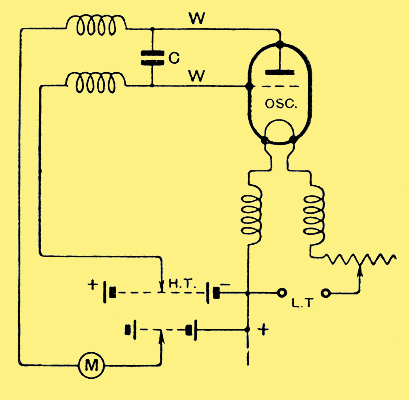
For generating waves shorter than one metre, an electron oscillation circuit must be used. Note that positive HT is applied to the grid.
The point to notice is that the positive HT potential is applied to the grid, and a negative potential of lesser value is applied to the plate, which is rather an unconventional arrangement.
The dance of the electrons
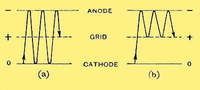
The cloud of electrons may 'dance' in time with the oscillations either between cathode and anode or grid and anode.
The actual way in which this arrangement functions does not seem to have been definitely settled so far, but a plausible explanation which fits the experimental facts is as follows:-
On switching on the circuit, a cloud of elections starts from the cathode and is attracted strongly towards the grid by the powerful positive potential thereon. Some of them are caught by the grid during their first flight, and take no part in the oscillatory action. Many, however, attain a high velocity and pass through the spaces between the grid wires, travelling towards the plate, where they are repelled by the negative potential thereon. If this latter potential is of the right value, the majority of the electrons just manage to reach within a short distance of its surface before their velocity is reduced to zero, when the positive charge on the grid again affects them and they are finally drawn back to it and absorbed. It the constants of the circuit connected to the electrodes are suitable, this rush of electrons (a rush of current; in fact, a transient) impulses the circuit, the return swing of which assists the retarding voltage upon the plate to return the electron cloud to-wards the grid. During this impulse the second return swing (again in the positive direction with respect to the cathode) helps the positive potential upon the grid to attract a further batch of electrons from the cathode, and may also retract many of those which had been repelled from the plate back towards it.
The net result is that clouds of electrons may 'dance' in time with the oscillations in the external circuit either between cathode and anode (a) above or between grid and plate (b) above. In either case the frequency and therefore the wavelength is dependent upon the time of swing of the electrons between the two electrodes in question. This time period is in its turn dependent upon the distance between those electrodes, and inversely proportional to the voltage between them. Since (under the same operating conditions) the distance between the grid and plate is less than that between the cathode and plate, the former method of oscillation gives rise to the shorter waves.
The HF potentials set up in the external circuit by the oscillating electron clouds may influence, via the changes or potential upon the electrodes, the time of swing. The result of this appears to be that in some circumstances the constants of the external circuit can affect the period of swing and therefore the wavelength, whilst in other circumstances this is determined solely by the geometry of the valve and the operating potentials, the constants of the external circuit merely affecting the output, by resonance with the electron oscillations.
In the former case the type of oscillation is referred to as the Gill-Morrell, and in the latter case as the Barkhausen-Kurz, from the names of the two investigators who in each case first demonstrated that particular type of oscillation. It is not easy to predict which type of oscillation will be produced in any particular case, but it may be said that in general a perfectly symmetrically constructed valve and low operating potentials will pre-dispose to Barkhausen-Kurz oscillations, whilst a slightly unsymmetrical valve with high operating potentials will pre-dispose to oscillations of the Gill-Morrell type. Oscillations of both types may co-exist simultaneously.
Referring to the practical side of the question, there is one rather serious drawback to the electron-oscillation method, i.e., it is very hard on the valve, as anyone might surmise who has had any experience of valves using high positive grid potentials. Consequently, only valves of the bright emitter type will stand up to the work for any length of time. For experimental purposes it is best to choose a small bright-emitter transmitting valve of robust and symmetrical construction. Voltages of from +200 to 300 volts may be applied to the grid, and from 0 to minus 100 to the anode/plate. A sudden change in the reading on the plate-current meter (M) will indicate that oscillation has commenced, when the bridge can be moved along the wires until maximum output is obtained, usually indicated by maximum reading on M. (In some cases of B-K oscillations there may be no indication at all on the meter M, whether the circuit is producing maximum available output or not. In these cases the indication is that the electron clouds are not actually reaching the plate, but are oscillating backwards and forwards about the grid.)
The Lecher wires (W) may conveniently be anything from 50 to 100 cm. in length and about 5 cm. apart. The stopping capacitor C may be of any value between 0.0001 and 0.001 μF. Oscillations of the B-K type do not necessarily produce oscillatory current in the plate circuit, so the plate circuit wire may be omitted, and the bridge wire substituted by a copper disc of 20-30 cm diameter arranged to slide along it, as shown at below. This form of the circuit is generally found to be very successful, and was originally devised by Pierret.
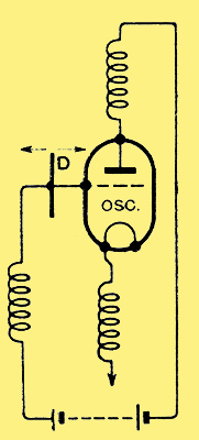
A copper disc 20 to 30 cms diameter, as shown at D arranged as a slider, can be successfully employed in the grid circuit of the electron-oscillation valve.
Still another form is shown below, in which the wire takes the form of a little vertical (approximately quarter-wave) 'aerial' attached to the grid terminal. Oscillations having been obtained by adjustments of the valve electrode voltages, the wire is adjusted in length until maximum output is obtained.
Another form of oscillator in which a vertical wire of quarter wavelength is attached to the grid terminal.
With suitable valves obtainable in this country AT40, AT40X, AT25, T15, etc.), the wavelengths obtained will generally be somewhere between 40-80 cm. The filament current will be found some what critical for maximum output, and the valve will generally have to be run somewhat over its rated filament voltage. Adjustment of the filament current changes the wavelength slightly, and may be used as a 'tuning' control when the circuit is used for reception purposes.
From the fact that the principle of electron-oscillators involves the employment of both an accelerating and a retarding field in what is really a diode with grid anode (since the plate only provides the retarding field), the use of a magnetic retarding held has been suggested and successfully tried.
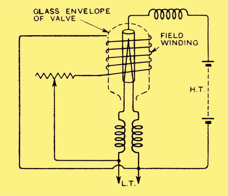
A diode with a winding outside the bulb to produce a retarding magnetic field. Five-centimetre waves have been produced by this circuit.
This arrangement was first successfully developed by Okabe, and dubbed by him the 'Magnetron'. In its essentials it consists of a diode, with a cylindrical anode, a DC field winding being arranged on the outside of the bulb so that a magnetic field is produced with its axis parallel with the axis of the anode and cathode. The effect of the field is to deflect the course of the electrons leaving the cathode, so that, instead of proceeding straight to the anode, they describe a spiral with the cathode as centre as shown diagrammatically below.
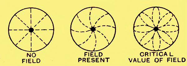
Electron formation in the Magnetron oscillator.
At a certain critical value of the field they just fail to reach the anode, and the action is practically the same as that discussed in connection with B-K and G-M oscillations in the triode. As the value of the field is increased, the anode current decreases, so that the anode voltage can be 'pushed' higher. As the strength of the field and the value of the anode voltage is increased, the generated wavelength becomes shorter. Okahe has succeeded by this means in producing 5 cm. waves. An arrangement used some time ago by the writer is shown below.
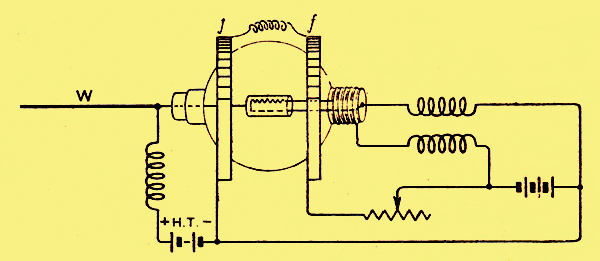
The author's 'Magnetron' arrangement with which wavelengths of from 30 to 60 cms are obtainable.
The valve is an old bright-emitter diode rectifier with a short aerial wire, W, and a pair of Helmholtz coils, f, f, providing the retarding field. The usual filament and anode chokes are, of course, employed. The object of using Helmholtz coils is that the field produced at their mutual geometrical centre (the electrode system or the valve) is very uniform; also they are easy to construct and to assemble on the valve. The distance apart of the coils in the axial plane is equal to the radius or the coil (mean values).
The waves produced by the magnetron arrangement are of the B-K type that is, they are not affected except as regards intensity by the constants of the external circuit. With the arrangement just described, wavelengths of 30-60 cm are obtainable, with anode voltages up to 300 Volts.
Receiver and transmitter used in experimental 18-centimetre wavelength telephony across the Channel on March 31st, 1931.
|