|
Commentary by John Linsley Hood. Linsley Hood, J. (1979) Valve & Transistor Amplifiers, Oxford: Newnes.
This is, in many ways, similar to the Leak TL 12 or the Radford STA 25 designs, but has some interesting design features, and achieves a very good performance with a relatively simple circuit layout. The quoted performance is 25 watts output at less than 0.1% THD, at 1 kHz, a bandwidth of 25 Hz-20 kHz, +0.2 dB, an input sensitivity of 480 mV for 25 W output, and a hum and noise figure of -85 dB referred to 20 watts output.
Structurally, the circuit consists of a high gain pentode input stage, with an HF phase compensation network, C2, R24, across its anode load resistor. This drives a pair of triodes, V2, V3, which act as a floating paraphase phase splitter, and which in turn drive an output push-pull pair of beam-tetrodes, V4, V5. (The output valves specified were STC type 5B/255Ms, but these were closely similar to the contemporary KT66s.) An innovative feature is the use of a resistor, R12, which is common to both V2 and V3 anode circuits to derive the paraphase input signal to V3. This leads to rather less loss of gain than the rather more common grid-derived paraphase input signal. A further subsidiary NFB loop, which contributes a further -10 dB to the total, and assists in achieving a good loop stability, is drawn from V2 anode circuit by way of R9. The circuit shown is for a 4 Ω output load, but for a 15 Ω load the values of R23 (4.7 kΩ) and C12 (100 pF) would be appropriate.
I consider this circuit to be an excellent example of valve audio design practice, along with the Brimar SP55 preamplifier, which could well serve as models to those designers wishing to return to valve operated audio systems.
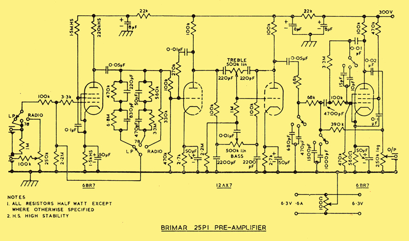
Pre-amplifier Specification
- Output: 500 mV maximum into 0.5 MΩ
- Sensitivity: Measured at 1 kHz, Bass and Treble controls flat, Gain control at maximum. Output of 500 mV
- Pickup: LP & 78: 20 mV
- Radio: 100 mV maximum sensitivity
- Equalising:
- Radio: Flat response
- Pickup: Compromise curves for most micro-groove and 78 rpm recording characteristics.
- Tone Controls: Continuously variable, referred to 1 kHz.
- Treble: -18 dB to +18 dB at 10 kHz.
- Bass: -13 dB to +15 dB at 50 Hz.
- Filters: Low pass filters switchable, high pass filters permanently connected.
- High Pass: (rumble) cut off:
- 30 Hz slope better than 12 dB/octave.
- Low Pass: (top cut) cut off:
- 5 kHz and 7.5 kHz slope tending to 18 dB/octave
- Distortion: Measured at 1 kHz, Bass and Treble controls flat, Gain control at maximum:
- For an output of 1,500 mV (i.e. three times specified maximum)
- Total harmonic distortion less than 0.05% on all inputs.
- Noise and Hum:
- Measured with Bass and Treble controls flat, Gain control at maximum:
- On all inputs either shorted or with 100 kΩ load:
- Better than 50 dB down at 400 mV output level.
Mains Transformer
- HT 450-0-450 @ 150 mA
- LT1 5 V 3 A
- LT2 6.3 V 3 A
- LT3 6.3 V 2 A
Output Transformer
- Partridge type P5352
- Savage type 5B29

Main Amplifier Specification
- Power Output:
- 25 Watts into load at 1 kHz.
- Sensitivity
- 480 mV for maximum output.
- Power Response
- ±0.2 dB from 25 Hz to 20 kHZ.
- Feedback
- Main Loop: 35 dB
- Total 40 dB
- Harmonic Distortion
- Total 0.1% at 25 Watts measured at 1 kHz.
- Hum and Noise
- -85 dB relative to 20 Watt level.
- Rise Time
- 6μS (10 kHz repetition rate)
- Phase Shift
- Output Impedance
- Valves
|