|
Taking Advantage of New Ratings for the KT66 Valve
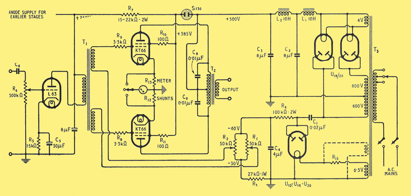
Complete circuit diagram of 50 Watt amplifier using KT66 valves with fixed bias
When the KT66 valve was first introduced in 1937 it was given maximum anode and screen voltage ratings of 400 and 300 respectively. At these voltages a pair of valves will provide an output of 30 watts with quiescent anode and screen dissipations of 21.5 and 0.75 Watts.
Recent investigations have shown that it is permissible to increase the anode and screen voltages to 500 and 400 respectively and the anode dissipation to 25 Watts. These new limits permit the design of an economical 50 Watt amplifier. This output represents an increase of nearly 70%, which is obtained with an anode supply voltage only 20% greater than that required for the 30 Watt amplifier.
Under the quiescent condition the dissipation is below the permitted maximum, though, due to the regulation of the supply, the voltages are slightly higher than the normal working limit. No ill effects will be experienced from this cause.
The comparative operating conditions per pair of valves unless otherwise stated are:
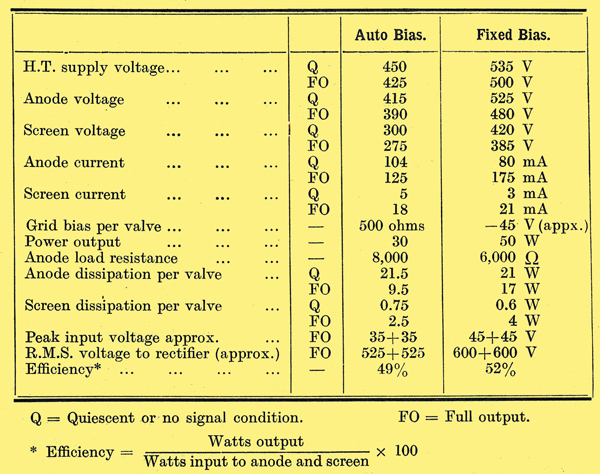
Small differences from the above data are to be expected with various pairs of valves.
The circuit used to obtain 50 Watts output is shown above, the two KT66 valves being driven from a low impedance triode via a push-pull transformer T1. The latter is not essential since the KT66 valves are not driven into the positive grid current region, and any of the recognized phase splitting arrangements are suitable, but the DC resistance from each KT66 control grid to earth should not greatly exceed 100,000 Ohms under the fixed bias conditions.
Independently adjustable bias controls, R1, R2, provide a bias supply variable from 30 to 60 Volts. The bias circuit is somewhat unorthodox in that it is taken from the anode supply transformer T3 via a small capacitor C1 of high working voltage. The maximum bias voltage obtainable is determined by the capacitance of C1 and the resistance of R1, R2, R3, and R4. This arrangement has the advantage that no special bias transformer is required and that a comparatively low bias voltage (of 60 volts) is obtainable from a high-voltage transformer without the use of resistances dissipating considerable power. This arrangement is suitable whenever a low impedance bias supply is not required, i.e. when the output valves are not driven into the positive grid current region. The value of the capacitor C1 may be increased or decreased to provide higher or lower voltages for use with other types of valves. It will be noticed that the rectifier filament is earthed and may be run from the 6.3 Volt amplifier heater supply with a resistance R5 dropping the voltage to 4 or 5 for the rectifier. Suitable resistances values are U10 2.33 Ohms, U4 0.9 Ohms, and U50 0.65 Ohms.
A considerable increase in anode and screen currents takes place with increasing signal input and a low-impedance HT supply is required. A choke input filter circuit using two low-resistance chokes L1, & L2, provides a hum-free supply of good regulation. When a small amount of hum can be tolerated at full output, the second choke and capacitor L2, C3 may be omitted.
Due to the large variation in a screen current between the quiescent and the full output conditions, a gas-filled cold-cathode diode, type 5130, must be used to supply the screen voltage. As the voltage drop across this diode does not change materially with varying current, the screens are maintained at approximately 115 Volts below the anode supply under all conditions of operation. This reduced voltage is also used to supply the earlier valves. The screen grids must not be connected directly to the 500 Volt supply.
The meter shunts R12; R12 are permanently connected in the cathode circuits of the KT66 valves and the meter measures the total cathode current of each output valve. The quiescent screen current (approx. 1.5 mA) is small compared to the anode current (approx. 40 mA), and may be safely ignored when adjusting the bias voltages by means of the resistances R1, R2. The actual quiescent current is not important and any value between 30 and 40 mA may be used. At lower currents 'crossover' distortion becomes evident and at higher currents the anode dissipation is increased unnecessarily. Both valves must of course be set to identical quiescent currents. A meter having a full-scale deflection with its shunts, of 100/150 mA is suitable.
The performance of the amplifier is illustrated by the curves below, and is suitable for small public address equipment and also makes an economical modulator for low power transmitters, being capable of providing 100% modulation for a 100 Watt carrier. It has a high efficiency and a lower quiescent dissipation than many other 50 Watt amplifiers. The use of fixed grid bias instead of the more usual cathode bias arrangement renders the amplifier rather less foolproof, and a meter is essential for adjusting the anode current and should preferably be built into the equipment. However, it is not essential that it should have a high accuracy and one of the miniature type is suitable.
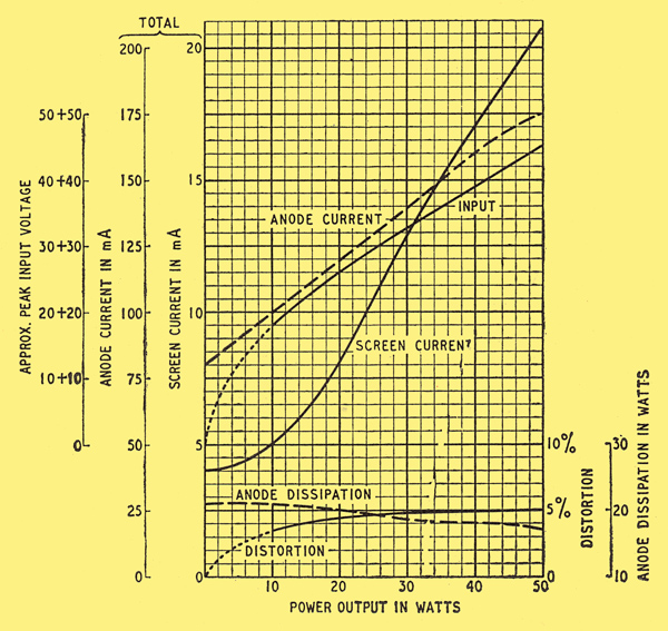
Performance curves of the amplifier operated in Class AB1 with Va=480V, Vg2=385V, Vg1=-45V, and an anode to anode load of 6,000 Ohms
|