|
Initial experiments, by Robert Watson-Watt and Arnold Wilkins, in 1935 demonstrated that the metal parts of an aircraft would reflect radio waves, and that these reflections could be received and used to indicate the presence of the aircraft by drawing a line on a CRT display. RDF (Radio Direction Finding) was born. The UK government recognised the importance of these early experiments and work began that culminated in the Chain Home RDF (RADAR) defence network for the British Isles in WW2.
In early 1936 a new line of research was commenced. This was to develop an RDF (RADAR) system that could be fitted to an aircraft for airborne use. The Chain Home RDF initially operated with transmitted pulses at a frequency of 6MHz and required massive aerial towers, and equipment weighing several tons. Requirements for an airborne system included low weight, low power consumption and small aerials. A new approach was needed.
Such small aerials required a high transmission frequency so that a half wave dipole would be of the order of one or two metres maximum length. At this time a frequency of 45 MHz was at the upper limits of what was technically possible outside the laboratory. Such high frequencies were being developed for use by a proposed television service. Special valves such as the SP41 and EF50 were developed for high frequency television reception.
The RDF development team obtained a single EMI 45MHz receiver chassis for airborne development trials. This receiver had a sensitivity greatly in excess of other receivers at this time when operating at 45MHz. Initially a ground based transmitter was used with an airborne receiver and ranges of up to 20km were achieved. This was sufficiently encouraging to embark on the production of an airborne transmitter.
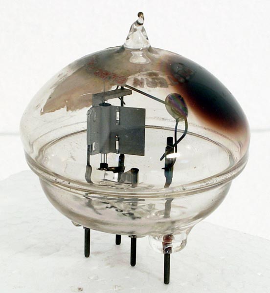
A transmitter was constructed using Western Electric 316A valves. An output power of several hundred watts was possible in pulse operation. The pulse length was 3 microseconds and the pulses were repeated one thousand times a second. The period between each pulse being the time available for the reception of any reflected signal. These trials proved encouraging and development continued.
The frequency of operation had to increase so that the aerial size could be reduced. A new transmitter was constructed. This used two 316A's in push-pull. Tests at various frequencies followed and 200MHz was chosen for the final version. To receive these Very High Frequency (VHF) signals a converter was built for the receiver. The original receiver on 45MHz then became the IF frequency. The front end used acorn valves for the initial frequency conversion. This pattern of equipment was fitted to a pair of RAF Avro Anson's and signals reflected from ships at nearly five kilometres distance were soon detected.
In September 1936 during a major Royal Navy exercise the aircraft carrier Courageous was detected at a range of approximately 10km. When the aircraft carrier launched planes to intercept the Anson, their detection by the Anson marked the first time aircraft reflections were seen on an airborne RADAR screen.
|