|
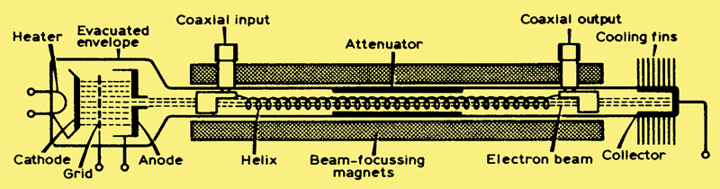
The essential features of a typical travelling wave tube
Introduction
In the past few years, several (radio) amateurs have employed travelling wave tubes (TWTS), colloquially known as 'twits', as microwave power amplifiers. The main attraction of these devices is their very high gain (30-60 dB), linear characteristics and 1-2 octave bandwidth. They are quite widely used professionally, but are still rather scarce in amateur circles. This article describes a little of the theory of TWTs, and explains how to use them, in the hope that more amateurs may be able to acquire and use these fascinating components.
The history of the TWT goes back to the second world war, when research into radar devices and techniques was at a particularly intense level. The TWT was invented in the Nuffield Laboratory Physics Department, Birmingham University (also the birthplace of the cavity magnetron) by Rudolf Kompfner. He was seeking an alternative which had a better noise performance than the klystron, and in a 1946 paper he explained his reasoning.
'One of the main reasons for the lack of sensitivity of the klystron as an amplifier is the inevitable energy exchange between the electron beam and the electric field in the rhumbatrons (resonators) ...It was therefore a very inviting thought to use the signal in the form of a travelling electric field (instead of a stationary one) and utilize the energy exchange between the travelling field and electrons which travel at about the same velocity.'
In December 1943 the first tube gave a gain of about 8 dB at a 9.1 cm wavelength, with a 13 dB noise figure. The work was later transferred to the Clarendon Laboratory, Oxford. Much of the mathematical analysis of TWT operation was developed by John R. Pierce, of Bell Labs[1], and in 1947 Kompfner joined Pierce to continue TWT research.
Nowadays, TWTS are by far the most widely-used of microwave tubes, and are employed extensively in communication and radar systems. They are especially suited to airborne applications, where their small size and low weight are valuable. Satellite communication systems are another extremely important application, for the same reasons.
Recognition
Practical travelling wave tube amplifiers (TWTAs) have applications in both receiver and transmitter systems, and come in all shapes and sizes, but they all consist of three basic parts-the tube, the tube mount (which includes the beam focussing magnets) and the power supply.
When used as receiver RF amplifiers they are characterized by high gain, low noise figure and wide bandwidth, and are known as low noise amplifiers (LNAS). These usually come with tube, mount and power supply in one integral unit, with no external adjustments to make-just input socket, output socket and mains supply connections. A typical LNA has an octave bandwidth (e.g. 2-4 GHz), 30 dB gain, 8 dB noise figure, and a saturated power output of 10 mW, within a volume of 2 in by 2 in by 10 in.
Transmitter TWTAs are naturally somewhat bulkier, and often have the power supplies as a separate unit. Medium-power tubes have outputs of up to about 10 W, while high-power tubes deliver several hundred watts. Such tubes have gains of the order of 30 or 40 dB, and bandwidths of up to an octave. The major manufacturers of TWTS are EMI-Varian, Ferranti, EEV, Hughes, STC, Litton, Raytheon, Siemens, Watkins-Johnson and Thomson-CSF:
Construction
The features of a typical TWT are shown in the top diagram. The electron beam is provided by an electron gun which is very similar to those used in CRTs, though the beam current is much larger. Electrons from a heated cathode are accelerated towards the anode, which is held at a high positive potential with respect to the cathode, and a proportion pass through a hole in the anode to produce the beam. Some tubes have a grid between the cathode and anode, at a few tens of volts (adjustable) negative with respect to the cathode, the function of which is to control the beam current. The electron beam travels down the tube, inside the helix, to the collector, which is maintained at a high voltage referred to the cathode. The helix is also held at a high potential, but the helix current is low because of the beam focussing.
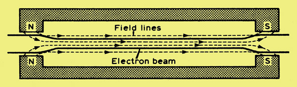
The focussing of the electron beam by the magnetic field
As is shown above, this focussing is achieved by a magnet (either a solenoid electromagnet or permanent magnets) round the outside of the tube. An electron with a component of velocity perpendicular to the magnetic field lines experiences a restoring force tending to bring back its direction parallel to the field lines.
To achieve good focussing by this method requires a very large magnetic field, which can mean a bulky, heavy magnet. However, the arrangement usually employed is called periodic permanent magnet (PPM) focussing, in which a number of toroidal permanent magnets of alternating polarity is arranged along the tube, as is shown below; this figure also shows the contour of the beam.
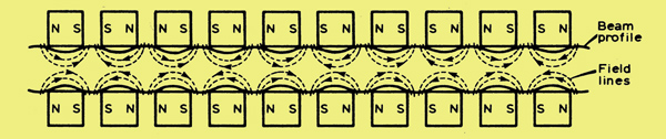
Periodic permanent magnet focussing
This arrangement reduces enormously the required weight of magnet (under ideal conditions by a factor 1/N*2; where N is the number of magnets used). The alternative method, solenoid focussing, is generally only used in high-power earth station TWTS, where size and weight are unimportant.
The input to, and output from, the helix are via coaxial connectors, or occasionally via waveguide. In practice, it is impossible to provide a perfect match at these transitions, especially over a wide bandwidth, so an attenuator is used to prevent the energy reflected back down the helix causing instability. This usually takes the form of a resistive coating on the outside of the central portion of the tube, though a physical discontinuity in the helix is also used in some cases. The attenuator reduces the RF input signal, as well as any reflected signal, to nearly zero, but the electron bunches set up by the signal are unaffected.
The helix itself is a fairly delicate structure, and must be provided with adequate thermal dissipation to prevent damage. In medium-power tubes, the helix is often supported on a beryllia or alumina substrate, but for high-power TWTS, alternative slow-wave structures are employed (e.g. coupled cavities), though usually at the expense of bandwidth. In this form, the TWT resembles a klystron amplifier.
Theory
The essential principle of operation of a TWT lies in the interaction between an electron beam and an RF signal. The velocity, v, of an electron beam is given by:
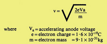
An anode voltage of 5 kV gives an electron velocity of 4.2 x 10⁷ m/s. The signal would normally travel at c, the velocity of light (3x10⁸ m/s), which is much faster than any 'reasonable' electron beam (relativistic effects mean that the electron mass actually increases as its velocity approaches c, so that achieving electron velocities approaching c is a complicated business), If, however, the signal can be slowed down to the same velocity as the electron beam, it is possible to obtain amplification of the signal by virtue of its interaction with the beam. This is usually achieved using the helix electrode, which is simply a spiral of wire around the electron beam,
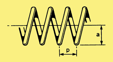
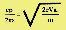
The geometry of the helix
Without the helix, the signal would travel at a velocity c. With the helix, the axial signal velocity is approximately c x (p /2πa) where a, p are shown above, so the signal is slowed by the factor p/2πa. Note that this is independent of signal frequency. The signal travelling along the helix is known as a slow wave, and the helix is referred to as a slow-wave structure, The condition for equal slow-wave and electron-beam velocities is therefore approximately
The interaction between the beam and the slow wave takes the form of 'velocity modulation' of the beam (i.e. some electrons are accelerated and some retarded) forming electron bunches within the beam. The beam current therefore becomes modulated by the RF signal, and the bunches react with the RF fields associated with the slow wave travelling down the helix, resulting in a net transfer of energy from the beam to the signal, and consequent amplification. Since there are no resonant structures involved in this interaction, amplification is obtained over a wide bandwidth. In fact the principal factors which limit bandwidth are the input/output coupling arrangements.
It should also be mentioned that it is possible to construct an oscillator, utilizing the so-called backward wave, whose energy travels in the reverse direction to the electron beam. These tubes are known as backward wave oscillators (BWOs) and have the advantage of a very wide tunable range (an octave or more). They have been used extensively in swept frequency sources (sweepers), but are rapidly being displaced by Gunn diodes and, more recently, transistor sources.
Operation
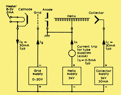
Power supply arrangements for a typical travelling wave tube
The power supply arrangements for a typical TWT are shown in above. The voltages and currents given are for a 10 W output tube, but the alignment details apply to almost all tubes.
However, manufacturers' data regarding electrode voltages and tube operating conditions should always be referred to before running any particular tube.
It is very important that a suitable matched load be connected to the output of the amplifier, as the power reflected from any mismatch at the output is dissipated in the helix and can burn it out. For the same reason the antenna must be properly matched.
The beam current is controlled by the grid-cathode voltage. In modern TWTS, the beam focussing is preset and no adjustment is necessary, but if the focussing is adjustable the tube should be run initially at a low beam (collector) current, and the beam focussing magnets adjusted for minimum helix current. The helix voltage should also be set for minimum helix current.
With the tube running at its specified collector current, RF drive can be applied. The collector current will hardly change, but the helix voltage should be set for maximum output consistent with not exceeding the tube voltage or helix current ratings. If the focussing is adjustable this should be readjusted for minimum helix current, since the RF drive will defocus the beam slightly.
As the helix is fragile and will not dissipate more than a certain power without damage, the helix current should be metered, and a current trip incorporated to cut the power supplies to the tube if the helix current becomes excessive. The EHT supplies to the tube should be well smoothed, since ripple will phase-modulate the output and give a rough note.
If the collector dissipates more than about 100 W it may be necessary to use a blower to cool the collector end of the tube. Typical efficiency of the TWTA is about 10 per cent, though some modern tubes may reach 40 per cent.
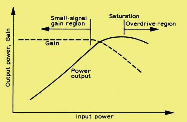
The transfer characteristic of a travelling wave tube amplifier
The transfer characteristic is essentially linear, which permits the tube to be used to amplify SSB - one of its great advantages in an amateur context. As the input is increased, however, the amplifier saturates. There is no harm to the tube in operating at saturated output power, except that amplification is no longer linear, although if appreciable harmonic power is generated this may be reflected at the output transition and damage the helix through over dissipation.
The output from the amplifier can also be amplitude-modulated by a signal on the grid, but the attendant phase modulation is quite high; this method is not normally used to produce a great depth of modulation, other than to operate the TWT in the pulsed mode. This is because at some voltages between maximum and minimum output, beam interception by the helix occurs, which causes excessive helix dissipation unless the transitions are rapid.
Phase modulation is obtained by varying the helix voltage over a small range. Typically, plus or minus 100V from 2 kV nominal helix voltage will give 2 rad phase shift, with 1-2 dB reduction in output, which occurs because the gain is very sensitive to cathode-helix voltage.
It is very useful to include some permanent form of power monitor of the output from the amplifier. This can conveniently take the form of a directional coupler and diode detector.
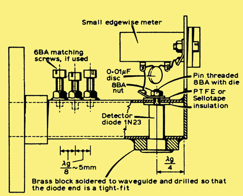
A simple 10 GHz power monitor
Above is a simple 10 GHz version of a detector/power meter, which is extremely versatile. In its simplest form the detector uses a small cheap edgewise meter. which can be calibrated roughly. A more accurate detector can be made by replacing the meter with a suitable socket (BNC) and connecting the detector across a suitable multi-range milliammeter.
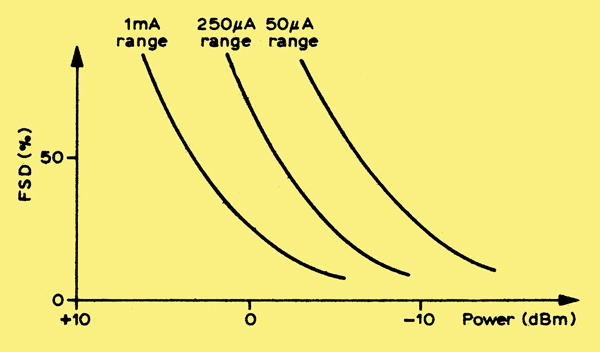
The form of the calibration chart for the power meter
The calibration chart plots percentage full-scale deflection of the meter vs incident power. Matching screws, if fitted, are adjusted to match the detector and then locked securely in position. Note that the calibration is strictly correct at only one frequency, and is somewhat dependent upon meter resistance. The dynamic range of this power meter can be vastly extended using a calibrated variable attenuator, or directional coupler. Suitable WG16 directional couplers are described in[2].
It is most important that anyone contemplating generating more than a few milliwatts of power at microwave frequencies should make sure they understand potential radiation hazards. Power densities are greatest in open-ended waveguide or around dish feeds, and especial care is required in these regions. The diode detector should be used to check around flanges and lengths of flexible waveguide, both of which can become leaky without showing external signs of damage.
Conclusion
The problem unfortunately still remains that TWTS are very difficult to acquire. Nevertheless, their high power output, high gain, and ease of operation make them the ideal way to run power at frequencies above about 4 GHz, where conventional tubes like the 2C39A run out of steam, and they represent practically the only way to run high-power SSB. It is relatively easy to generate the 1 mW or so of SSB at microwave frequencies required to drive most TWTS[3], which will produce over 1 W of power. This, in conjunction with high-gain antennas, permits advantage to be taken of tropospheric scatter as a reliable propagation mode, and takes amateur microwaves from hilltop-to-hilltop operating to the serious pursuit of DX over non-optical paths.
References
- Travelling Wave Tubes, J. R. Pierce. Bell Lab Series. D Van Nostrand (1950).
- VHF/UHF Manual, 3rd edn, p8, 14. RSGB Publications.
- Microwave Column, RadCom January, April 1979.
Acknowledgement
The author is indebted to his colleagues on the RSGB Microwave Committee for their advice and assistance, in particular G3YGF, G3JVL and G3RPE.
|