|
Contents
(Within the text click a heading to return here)
The Diode Valve
The Triode Valve
Valve Construction
The Diode Valve
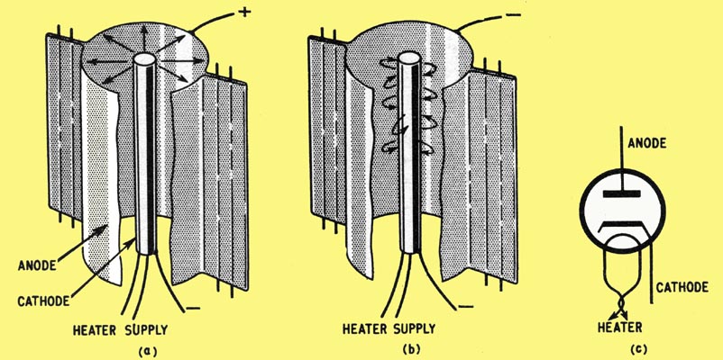
The thermionic diode or two-electrode valve. The general form of construction Is shown in (a). Electrons emitted from the cathode are attracted to the anode because the latter has a positive charge. In (b) we see the effect of applying a negative charge to the anode the free electrons are repelled and remain in the vicinity of cathode. The circuit symbol for an indirectly heated diode is shown in (c).
A quick look at the history of the electronic valve is of great interest. The simplest valve, now called the diode or two electrode valve, was first made, in England, by Fleming. He had read a paper about darkening of electric lamp glass envelopes, written by the American inventor Edison. Edison reported that, whatever was coming off the glowing carbon filament and darkening the envelope could be stopped by sealing into the bulb a small plate, and connecting this to the positive side of the filament. Fleming developed his valve using this idea.
The important action upon which valves are based is called the thermionic effect. This is the fact that electrons can be boiled off the surface of a heated substance and the electrons then form a cloud in the space adjacent to the surface.
Now, electrons is the name we give to tiny particles of negative electricity, and they are attracted to a positive charge (and if you remember, repelled by other negative charges). The cloud of electrons will not move very far unless as much air as possible is removed. This means a vacuum must be produced, and under these conditions you probably agree that it will be easy to attract the electrons across the vacuum to a positive plate nearby. This plate is called the anode. If the plate is charged negatively, no electrons stream across. This is because none is being emitted by the cold plate, and those at the hot filament are repelled by its negative charge.
You have just covered all the important ideas concerning the diode valve. It is quite easy to see now - why the valve allows current through in one direction only. (Hence the name valve.) The electron emitter is called the cathode, and it is either a filament heated directly by an electric current, or more commonly now, an indirectly heated surface. In the later case the heater is separate from the cathode itself, acting rather like a small electric fire.
Moving on to a remarkable development of the diode, we will see how much of electronics was made possible by the addition of a third electrode. The idea of having free charges of electricity moving through a vacuum from one electrode to another begs the question: what would happen if other electrodes are placed in the electron stream? The more complicated valves which make use of these extra electrodes give rise to the types known as triodes, tetrodes, pentodes - and so on, together with the rather specialised variety known as cathode ray tubes.
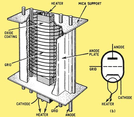
This cut-away view of a triode electrode assembly shows the three main electrodes, plus the heater. (b) Circuit symbol for an indirectly heated triode.
The addition of one further electrode into the space between the cathode and the anode makes three altogether, and accounts for the name, triode.
Suppose a metal mesh is placed between the cathode and the anode. Electrons will flow through the gaps in this mesh, or grid and reach the positive anode as before. But if an electric potential is placed between this grid and the cathode, the flow of electrons will be greatly affected. If there is a negative voltage on the grid, the electrons will be repelled and slowed down, and fewer will reach the anode. In fact, if the grid is made sufficiently negative, all the electrons will be repelled back, and none will pass to the anode, despite its positive potential. We say the valve is cut of or in electronics, switched off at the grid, when this condition occurs.
The importance of this third electrode can be appreciated now: small changes of the grid voltage can produce much greater changes in the current passing through the valve. Not without justification is this third electrode frequently referred to as the control grid. You can see that a triode can be looked on as a voltage-change to current-change converter, and is in fact, an amplifier of signals. Amplifications of 50 to 100 times are possible with modern valves.
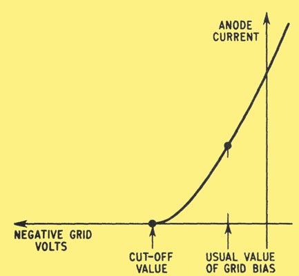
The graph shows how the current flowing through a triode is influenced by the voltage applied to the control grid. As the grid is made more negative, a point is finally reached where the anode current ceases altogether. This is the 'cut-off' value of grid bias.
In practice, the grid is held at a small negative voltage with respect to the cathode. This is called the grid bias and the small signal voltage variations increase and decrease the value of the grid voltage about this point. Only in exceptional cases is the grid allowed to rise positive to the cathode, and therefore attract electrons to itself.
Most substances must be heated to a very high temperature before in appreciable number of electrons are given off. Early valves used tungsten filaments, which had to be heated to 2,200 Centigrade before electrons were emitted. They glowed like an electric lamp, and much power was consumed to heat them.
An alloy of tungsten and thorium came into use next, and operated at about 1,600C. The great break-through came when oxide coated filaments (and soon after, separate cathodes) became possible. The filaments of directly heated valves are usually made of tungsten. The separate cathodes are cylinders of nickel or molybdenum. The carbonate of the metal barium or strontium is painted onto the cathode, and this is heated to quite high temperatures during the pumping of the vacuum, which forms the oxide. This delicate oxide coating emits electrons readily at temperatures of about 750C, so that only a dull red heat is required.
The anode plate is usually of nickel or molybdenum, blackened to radiate heat. It is held by welding thick wires to it, these passing through mica end supports wedged into the glass envelope. In use, the bombardment of the anode by the speeding electrons produces heat. The anode must remain cool, or electrons might be emitted from it also, although other damage is usually done long before the temperature rises to the electron emission point.
Now to the grid. There are very few materials suitable for this electrode, and again tungsten or molybdenum are the usual metals employed. The grid is formed by winding a spiral of fine wire round two stout support wires (held in the mica pieces).
|