|
In common with many of our designs, all the components, except for the transformers, fit onto a single printed circuit board.
Of late (1984) there seems to be a renewed interest among audio enthusiasts for valves. Valve amplifiers are 'in'. Those in the know now say, as, indeed, they always have, that valves sound better than transistors. The fact that we have designed a valve amplifier does not necessarily mean that this is our opinion. Appreciation of sounds is, in any case, purely a personal matter so everybody simply has to decide what he personally prefers. That is now very easy, at least for anybody who builds this 'good-old-fashioned' amplifier it is.
Specifications
- Nominal output power: 10 watt into 4, 8 or 16 ohm
- Maximum output power: 12 watt harmonic distortion: 0.5% (50 Hz - 20 kHz)
- Signal/noise ratio: depends on individual circumstances
- Input sensitivity: 200 mV RMS
- Input impedance: 1 MΩ
- Damping factor: 25
- Frequency characteristic: 20 Hz. - 40 kHz ±1 dB (at 1 watt)
- Feedback: about 26 dB
With the invention of the transistor, valves lost their 'monopoly' as the active element in electronics. They have never completely disappeared, however, and for many applications, especially where a lot of power has to be handled, they are indispensable. Even in cases where the transistor might seem to be the logical choice, however, valves are still to be found. Some audiophiles, as we have already mentioned, prefer tubes but amateur radio users have also refused to let the 'new-fangled' transistor supersede their beloved valves.
The HF people favour tubes for their indestructibility and power handling characteristics, the audio enthusiasts for other reasons. They consider that valves have a different (and better) sound than transistors. Whether this is so or not there is certainly a resurgence in interest for valves. Just one of the indications of this is seen in the increasing number of valve power stages in the high-end sector.
We have also been bitten by the valve bug, as witnessed by this amplifier. The power output is quite small (10 watt) but this could be just the beginning. We may even come up with a heavier version at some stage in the future (but that is not a promise). The valves themselves are still readily available so that will not be a problem; the ones we use are actually advertised in this issue.
A classic circuit
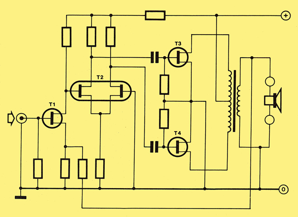
If it were possible to make this amplifier with semiconductors this is how it would look. Clearly the design itself is very simple.
Those who grew up with valves will recognise the 'classic' layout of the circuit diagram. It is shown in a modernised form above, this is how it would look if it could be built with semiconductors. Our showing it like this is, of course, a complete reversal of the situation of a quarter century ago when designers converted the new-fashioned transistor circuit diagrams back to valves in order to understand what was going on.
Compared to modern circuits, the layout above looks extremely simple. All it has, basically, is a preamplifier stage (T1), a differential stage (T2) and two power transistors. Such a layout would be impossible to achieve with normal bipolar transistors; at very least a few drivers would have to be included. This is one obvious advantage that valves have. As far as modern semiconductors are concerned, only the MOSFET can be considered in any way comparable to valves.
Having seen how simple the circuit design is, we can now move on to the actual circuit diagram, as shown below.
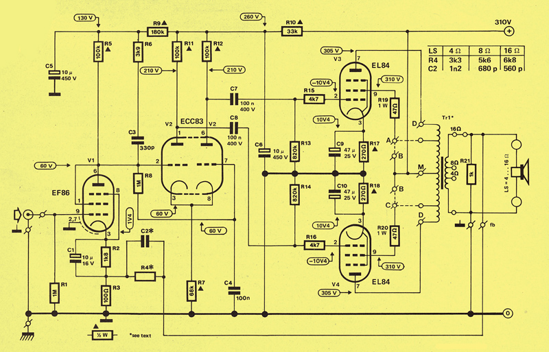
The circuit diagram for this amplifier is very unusual for Elektor. The reason for this is, of course, the fact that it contains four valves. Note that the values of C2 and R4 depend on the impedance of the loudspeaker used.
If we ignore compensation networks, de-coupling capacitors and so on, we see that the circuit is essentially the same as that of figure 1. An EF86 pentode (V1) acts as a preamplifier, a double-triode ECC83 (V2) forms a differential amplifier, and finally two EL84 pentodes make up a push-pull stage, that drives the loudspeaker via an output transformer.
The EF86 is connected as a triode and has a gain of about twenty times. Filter R6/C3, which is in parallel with anode resistor R5, ensures that the gain is reduced at high frequencies. This is necessary in order to achieve stability. The phase shifting needed for driving the power elements (V3 and V4) is provided by the ECC83 double-triode with cathode coupling. This 'differential stage' is used because it keeps distortion to a minimum and enables a direct coupling to be made to the preamplifier tube. The reasoning is easy to understand knowing that the grids in the double-triode must have a positive potential due to the large voltage drop across cathode resistor R7.
The power stage consists of a conventional push-pull circuit with two EL84s set to an anode voltage of 310 V. There is no need for V3 and V4 to be paired as each has its own cathode resistor (R17, R18). The improvement here would, in any case, be very small. The resistors in series with the grids (R15, R16) and the screen grids (R19, R20) improve the stability. Some output transformers have special screen grid tap-off points on the primary side. If these are available points A and C should be connected to them and the power stage will then be 'ultra-linear'. If the transformer used does not have this facility A and C should simply be connected to the positive supply at points B.
The signal from the secondary side of the output transformer is fed back to the non-decoupled part of the cathode resistor of V1. The values given to the feedback network (C2/R4) depend on the impedance of the loudspeaker used. The relevant values are given in the table at the top right-hand corner of figure 2.
The power supply is straightforward and follows the well-known transformer, bridge rectifier, electrolytic, formula. In this case we have used a supply transformer intended for use with valves. This has two secondary windings to provide the anode voltage of 260 V at a minimum of 75 mA and the filament current of 2 A at 6.3 V.
Construction
Although this sort of project would have been constructed differently before, there is now no reason why it cannot be mounted, as a transistor amplifier would be, on a printed circuit board. The valve mounting sockets for insertion into printed circuit boards have been available for a long time and the other components are the same as a modern amplifier would use.
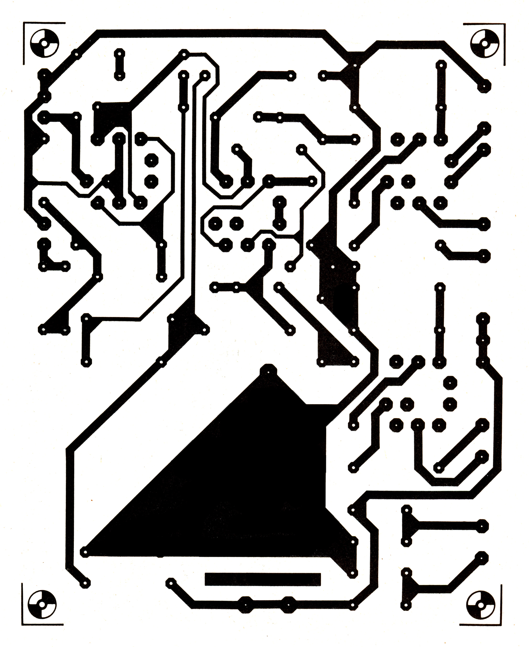
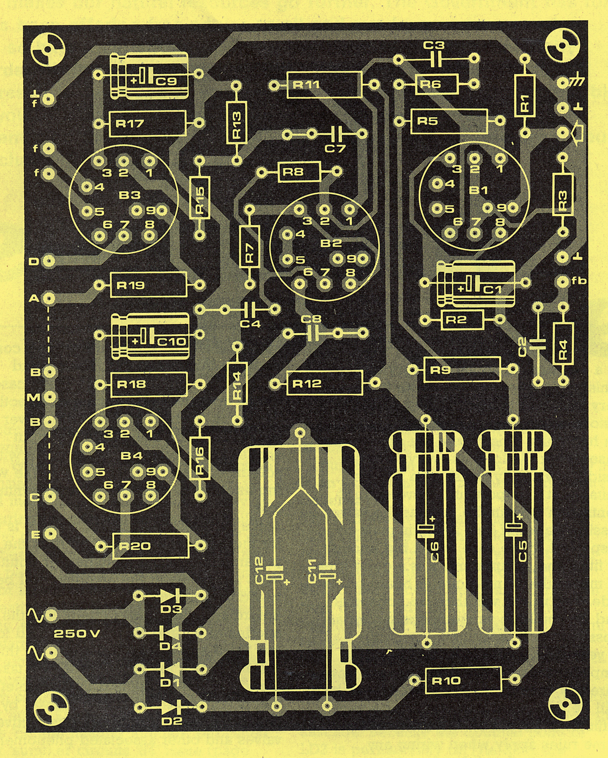
The printed circuit board that we have designed for this project is seen in figure 3. In spite of its compactness everything fits on the board, except for the two transformers and R21 (which is soldered across the loudspeaker terminals). In general, construction is just the same as for any other Elektor project but there are a few points to note. The board does not contain any tracks to feed the valve heaters so these must be wired by hand.
Make sure the cable used for this is capable of handling the heater current of 2 A. It is also wise to twist these two wires together. The heater connections are pins 4 and 5 for V1, V3 and V4, but pins 4, 5 (already joined on the board) and 9 for V2.
Plenty of room has been left on the board for mounting smoothing capacitors C11 and C12. We used a double capacitor here (2 x 50 μF 450 V in a single case) but a single 100 μF 450 V type may be used instead.
When fitting the components to the printed circuit board simply follow the sequence normally used. The valves are delicate, of course, so fit them last.
We have already mentioned the transformers briefly. The mains transformer must have at least two different secondary windings as we need 250 V at 75 mA and 6.3 V at 2 A. The output transformer must have an impedance of 2 x 4 kΩ at the primary side, preferably with screen-grid tap-off points. The impedance at the secondary side depends on the loudspeaker that is to be used. Well-informed suppliers will know what you want if you just ask for a 10 watt valve output transformer, or a transformer for a 2 x EL84 push-pull stage. If you were in the habit of 'salvaging' parts from radios when valves were in fashion there may be a suitable transformer lying at the bottom of you 'junkbox'. Don't reject it simply because of its vintage; it may be just what is needed.
Case and wiring
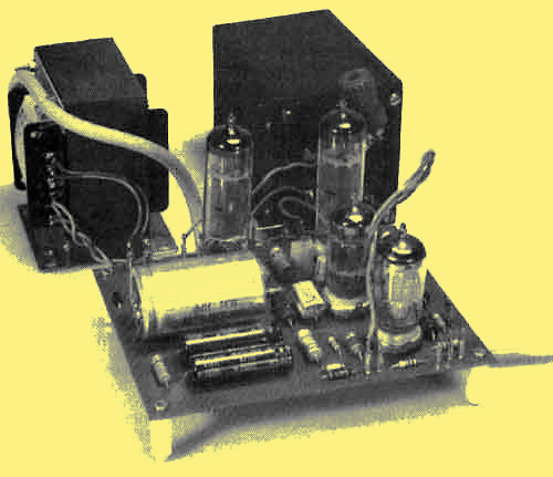
In a mechanical sense it is very easy to 'finish' this amplifier and make it into a very attractive project. Unlike power transistors, valves do not have to be mounted on heat-sinks. This makes the choice of a case easier. As long as everything fits inside, any sturdy metal case will be suitable. It is important to have enough ventilation slots in the case as the valves dissipate a lot of heat and this must be dispersed. If the case is just big enough to fit all the components it is a good idea to mount the printed circuit board on its side. The valves will then be horizontal and can pick up as much cooling air as possible.
A very important part of building any amplifier is the wiring. If this is not done carefully the chances are that a lot of hum will be generated and that can be very difficult to get rid of. In principle the same rules apply when wiring any amplifier, whether it has transistors or valves. The most important points are:
- Always use a single central ground point and wire all the amplifier's ground connections directly to this. The ground should be connected to the metal case either from the central point or directly at the input; try both and use whichever gives less hum. Lines from the input socket to the board must be made with screened cable. Finally, keep all the wiring as short as possible so as to minimise loss.
- Make sure that the correct polarity is used for the feedback connection from the output amplifier. If the loudspeaker connections are reversed the amplifier will be heard to oscillate.
- Before applying power check that the anodes of V3 and V 4 are connected to +ve (via Tr1 if applicable). Failure to do this will mean that the screen grid will take on the job of the anode and this is something that is not recommended (not even by 'Murphy's handbook of self-destructive valves and other associated phenomena'!).
Final points
By now the printed circuit board should be completely assembled and all the appropriate 'bits and pieces' should be correctly wired up. It is time for the 'acid test'. When power is applied to the amplifier it should work properly. No calibration or adjustment is needed.
Before use, however, check that the test voltages, shown in the circuit diagram, agree with those measured on the printed circuit board. If they do not, then recheck everything on the board and all the wiring because there is undoubtedly a mistake in it somewhere. If you want a stereo valve amplifier remember that all the components must be duplicated. This means that not only do you need two printed circuit boards but also two mains transformers and two output transformers.
Parts list
Resistors:
- R1, R8 = 1 MΩ 0.25 W
- R2 = 1 kΩ, 0.25 W
- R3 = 100 Ω, 0.25 W
- R4 = see figure 2
- R5, R11, R12 = 100 kΩ, 0.5 W
- R6 = 3k9 Ω, 0.25 W
- R7 = 68 kΩ, 0.5 W
- R9 = 180 kΩ, 0.5 W
- R10 = 33 kΩ, 0.5 W
- R13, R14 = 820 kΩ, 0.25 W
- R15, R16 = 4k7 Ω, 0.25 W
- R17, R18 = 270 Ω, 1 W (carbon)
- R19, R20 = 47 Ω, 1 W (carbon)
- R21 = 1 kΩ, 0.5 W
Capacitors:
- C1 = 10 μF 16 V
- C2 = see figure 2
- C3 = 330 pF (polyester)
- C4, C7, C8 = 100 nF 400 V
- C5, C6 = 10 μF 50 V
- C9, C10 = 47 μF 25 V
- C11, C12 = 50 μF 450 V (may be combined in a single package)
Semiconductors:
- D1 - D4 = 1N4007
Valves:
- V1 = EF86
- V2 = ECC83
- V3, V4 = EL84
Miscellaneous:
- F1 = fuse, 1 A slow blow (with holder)
- S1 = double-pole mains switch
- Tr1 = output transformer for 2 x EL84, primary: 2 x 4 kΩ preferably with screen grid tap-off points: secondary: 4, 8, or 16 Ω
- Tr2 = mains transformer; 250 V at 75 mA and 6.3 V at 2 A
- 4 off B9A socket for valves
- 1 off phono socket (for input)
- 2 off output sockets (e.g. wander plug type)
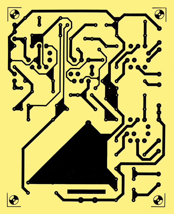
The printed circuit board template (copper side)

The printed circuit board template (top side)
|