|
Only one ECL86 is used in each channel of the three-watt stereophonic amplifier described in this section. The design is therefore very economical, but even so, a reasonably good quality of reproduction is achieved.
Bass-boost and treble-cut tone controls are provided. The sensitivity of the amplifier is sufficient for use with crystal pick-up heads, but a pre-amplifier will be necessary with magnetic pick-up heads.
Circuit Description
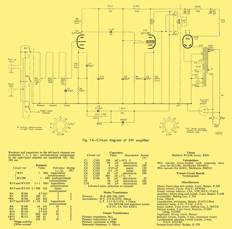
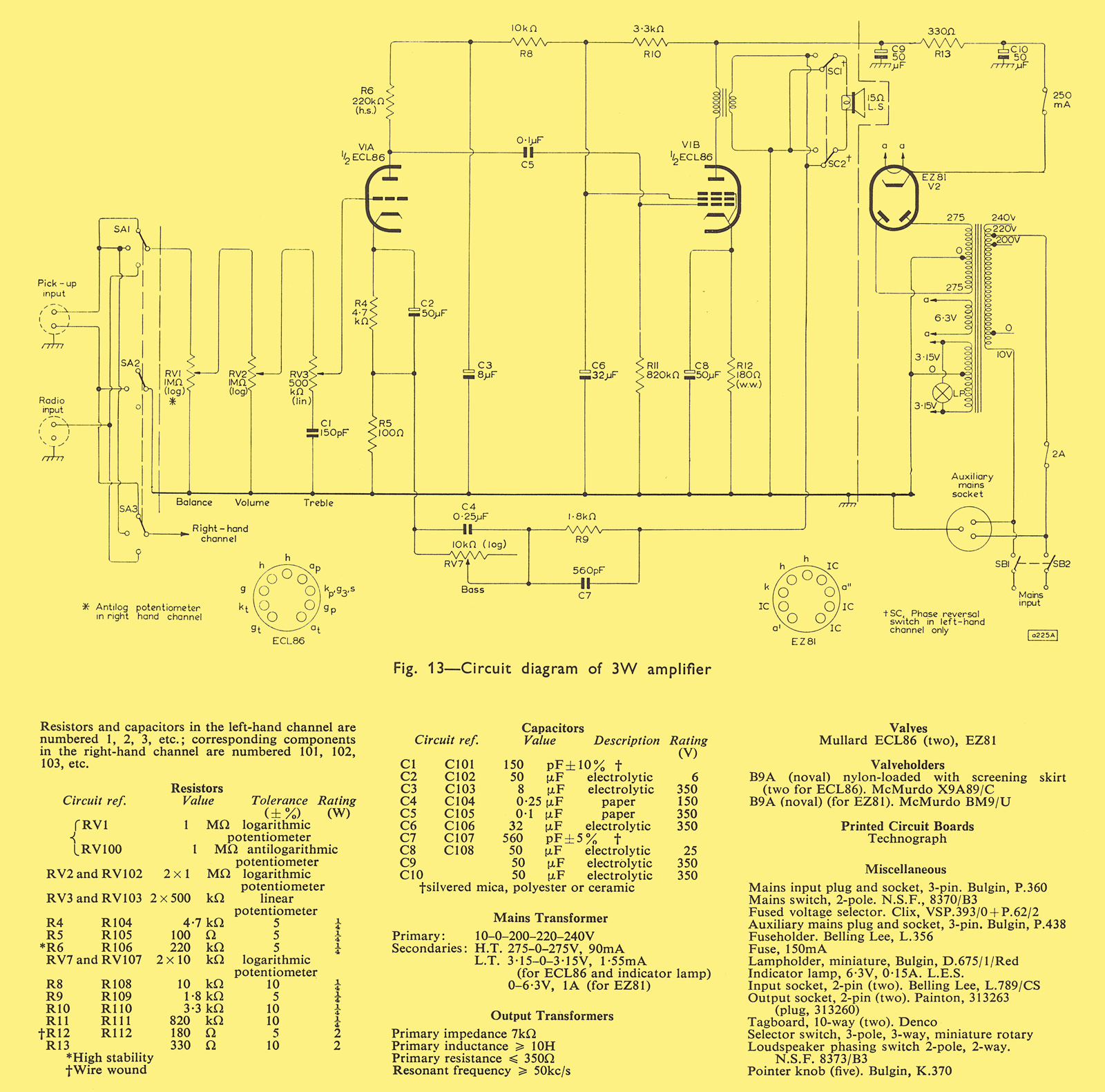
The circuit diagram for the three-watt amplifier is shown in Fig. 13. Only one channel is shown as the other channel is identical except for the loudspeaker phase-reversal switch. The complete amplifier uses two ECL86 and an EZ81 rectifier.
Input Selector Switch
The input stages of both channels are connected to the 3-way input selector switch SA, which provides facilities for stereophonic reproduction from a crystal or ceramic pick-up head, and dual-channel monophonic reproduction from a monophonic pick-up head or FM tuner.
Driver Stage
The triode section of one ECL86 is used in the first stage of the two-stage amplifier. The voltage gain of the stage is approximately 50 times.
Output Stage
The pentode section of the ECL86 is used in a class A output stage. The operating conditions are:
- Va = Vg2 = 250V
- Ia(o) = 36mA
- Ra = 7kΩ
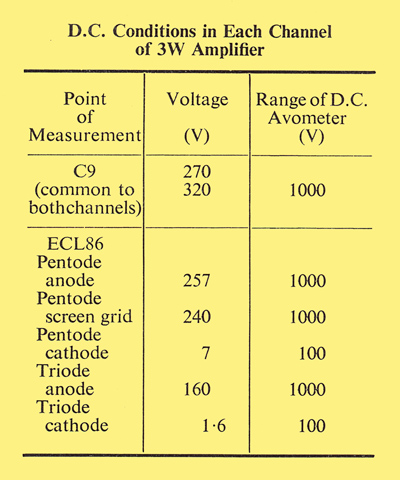
A cathode resistance of l70Ω (For speech or music signals, the standard value of 180Ω can be used.) provides the required bias of just over 7V. The ht line voltage should be chosen so that, allowing for the voltage dropped across the primary winding of the output transformer, the anode-to-cathode voltage is 250V. With the transformer used in the prototype amplifier, a line voltage of 270V is required.
The transformer used in the prototype amplifier has the following specifications :
- Primary inductance 10H
- Primary resistance 350Ω
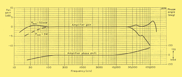
Frequency response characteristic of three Watt amplifier
The frequency response characteristic shown above will be achieved if the output transformer is free of resonances up to some 50 kHz If this is not so, it may be necessary to cut the treble response to ensure HF stability.
Negative Feedback
The amount of negative feedback taken from the secondary winding of the output transformer to the cathode of the driver stage is 18dB. The prototype amplifier is stable with a considerably greater amount of feedback, but 18dB is about the maximum which can be applied if the sensitivity is to be sufficient for use with crystal pick-up heads.
Tone-control Circuits
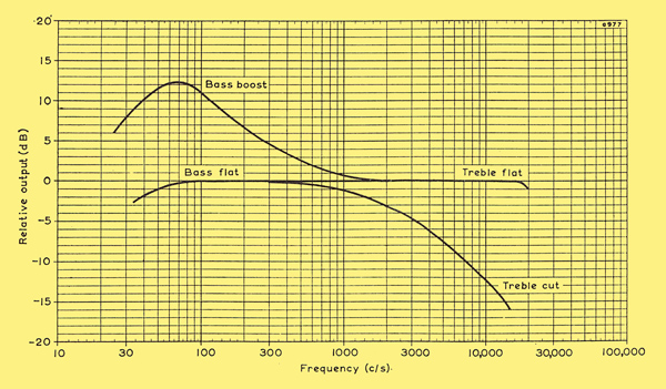
Tone control characteristic of three Watt amplifier
The parallel combination of a 0.25μF capacitor and a 10kΩ variable resistor in the feedback path provides continuously variable bass boost. A passive RC network in the input circuit gives continuously variable treble cut.
Balance Control
The balance control consists of a dual-ganged potentiometer, one track obeying a logarithmic law and the other an anti-logarithmic law.
Power Supply
The total HT current consumption of both channels of the amplifier is about 85mA, and an EZ81 is a suitable rectifier for these requirements.
Performance
Sensitivity
The sensitivity of the amplifier for an output power of 3W is 50mV without feedback and 400mV with feedback.
Frequency Response and Phase Shift
Graphs of the frequency response (for an output of 50mW) and the power response (for an output of 3W) for the 3W amplifier fed from a low-impedance source are presented. The amplifier phase shift is also shown in graphical form. The frequency response is flat to within 3dB from 15Hz to above 40kHz.
Because of the high value of the input capacitance of the triode, the hf response is somewhat dependent on the setting of the volume control (Miller feedback). The maximum loss of response at 10kHz is 5dB, and this is not large enough to be objectionable.
Harmonic Distortion
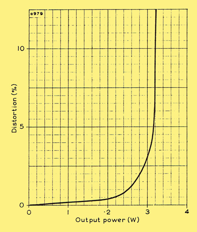
Total harmonic distortion plotted against output power for three Watt amplifier
Total harmonic distortion is plotted against output power. The distortion at an output power of 3W is 3%. The output power available with 10% harmonic distortion is 3.2W.
Output Impedance
The output impedance of the amplifier measured at the 15Ω terminals is 1.5Ω which gives a damping factor of 10.
Tone-control Characteristics
The response characteristics of the tone-control circuits are shown in Fig. 16. The maximum bass boost available at 70Hz is 12dB relative to the response at 1kHz and the maximum treble cut at 10kHz is 13dB.
Hum and Noise
The level of hum and noise in the prototype amplifier, measured with an open-circuited input and the tone controls set for a flat response, is better than 65dB below 3W.
Assembly of 3 Watt Amplifier
Since the wiring of the 3W amplifier is critical, the use of printed-circuit boards is advocated, and a printed-circuit version only is discussed.
Because of the high voltage gain of the ECL86, great care has been taken in the layout of the amplifier. In particular every precaution is taken to minimise stray capacitive coupling between the grid circuit of the triode section and the anode circuit of the pentode section of the ECL86. The valve-holders for the ECL86 should be nylon-loaded and skirted.
Construction of 3 Watt Amplifier Chassis
The chassis for the 3W amplifier is made from 16 SWG aluminium sheet. The dimensions (in inches) of the pieces are:
- Main chassis 16.5 x 12.5
- Cover plate 12.875 x 7.875
- Large screen 12.875 x 2.188
- Small screen 2.188 x 1.938
Each piece should be marked as shown, and the holes should be cut as indicated.
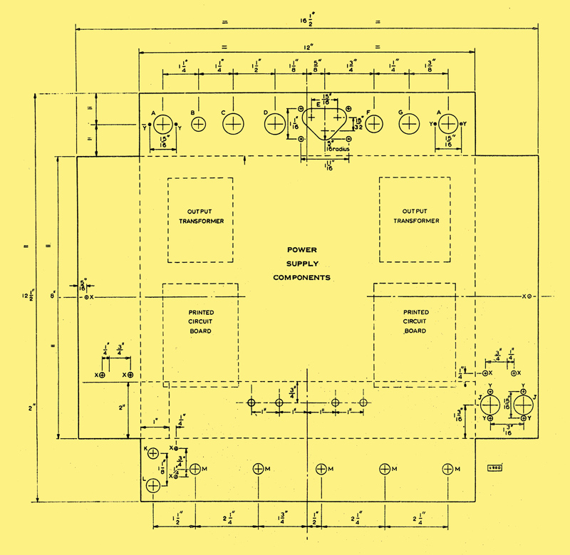
Main chassis
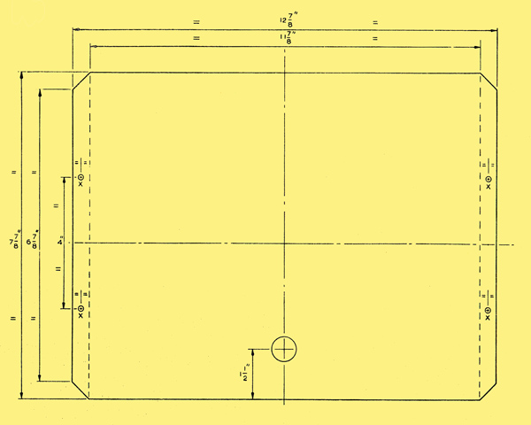
Base plate
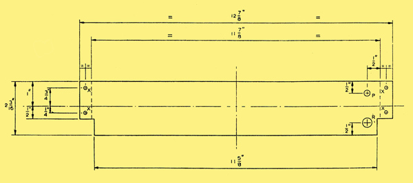
Large screen
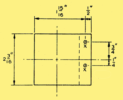
Small screen
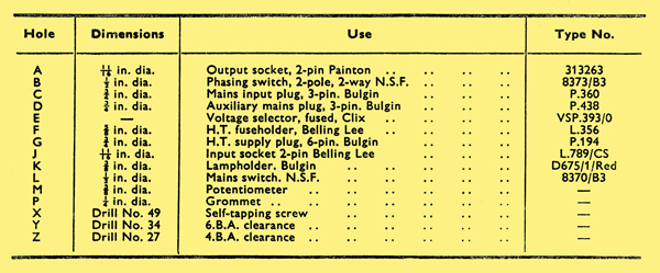
Key
|