|
The performance of the ten-watt stereophonic amplifier described in this section is exceptionally good and the amplifier can justifiably be placed in the 'high-quality' category. The use of the new ECL86 means that the cost of the amplifier is considerably less than that of amplifiers of similar performance currently available.
Fully comprehensive passive tone-control circuits are provided. The sensitivity of the amplifier is sufficient for use with crystal or ceramic pick-up heads, but a pre-amplifier will be necessary with magnetic pick-up heads.
Circuit Description
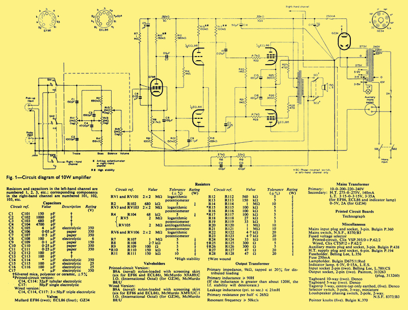
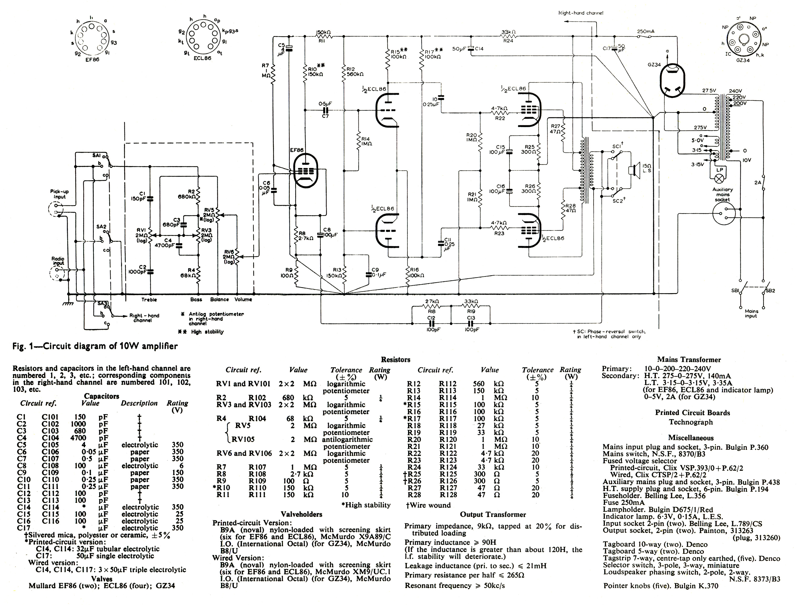
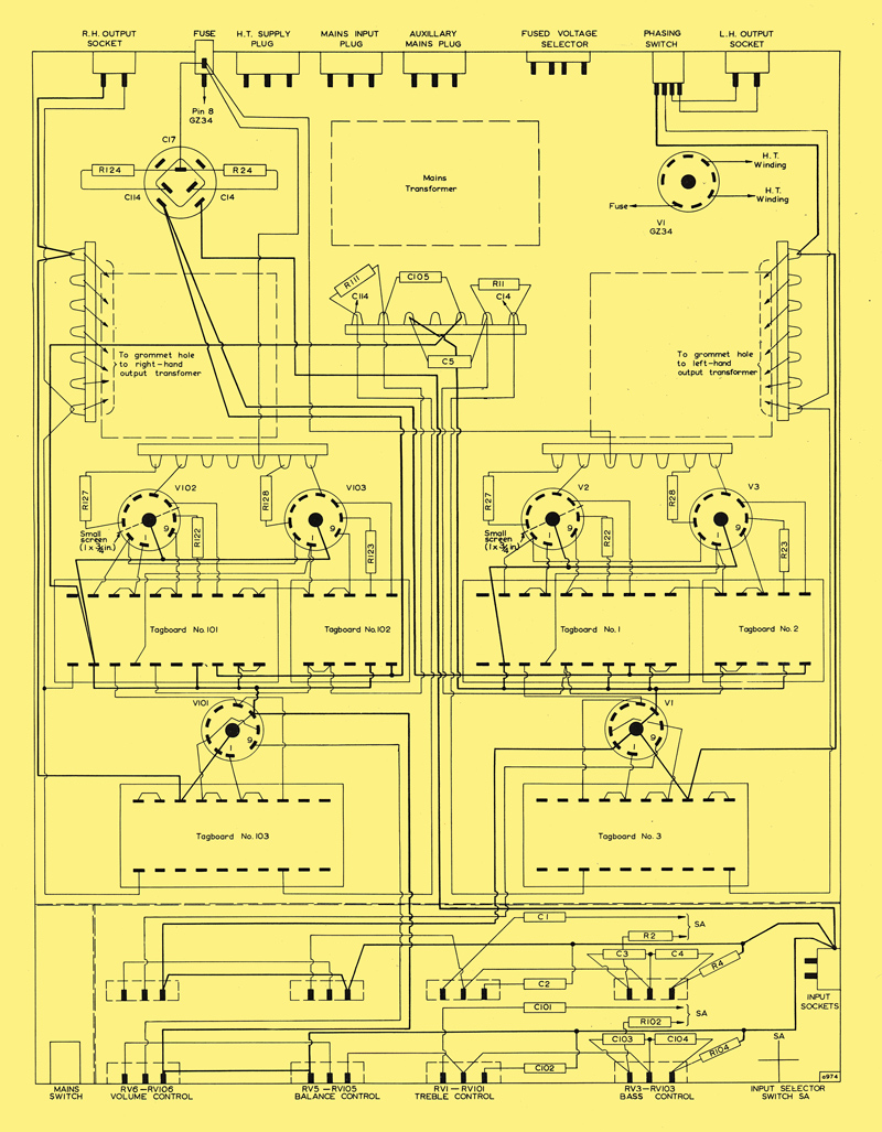
Circuit diagram of ten-Watt amplifier. [Note the full size image is 10Mb]
The design of the circuit shown in Fig. 1 is very similar to the well-known Mullard 'Five-Ten' monophonic amplifier. Only one channel and the common power supply are shown in Fig. 1 except for the loudspeaker phase reversal switch SC, the other channel is identical. The complete amplifier uses two EF86 and four ECL86; and a suitable rectifier is the GZ34.
Input Selector Switch
The input stages of both channels are connected to the 3-way input selector switch SA, which provides facilities for stereophonic reproduction from a crystal or ceramic pick-up head, and dual-channel monophonic reproduction from a monophonic pick-up head or fm tuner unit.
Input Stage
The input stage uses an EF86. The voltage gain of the stage is approximately 120 times. The stage is capacitively coupled to the phase splitter.
Phase Splitter
The phase splitter uses the triode sections of two ECL86 in a 'long-tailed' pair. Fixed bias to the grids is provided by a potential divider across the ht supply. The voltage gain is approximately 24 times per half.
Output Stage
The push-pull output stage uses the pentode sections of the two ECL86 opterating under class AB conditions with distributed loading (20% taps). With an anode-to-anode load of 9kΩ and an anode-to-cathode voltage of 300V, the distortion without feedback is less than 2% for outputs up to 10W.
The output transformer should be of the construction normally used in high-quality amplifiers. In particular, it should be free from any pronounced resonance up to about 50kHz The turns-ratio should be such that the anode-to-anode load is 9kΩ after allowing for winding resistances. The transformer used in the prototype has the following specifications:
- Total primary inductance 100H
- Primary resistance per half 265Ω
- Leakage inductance (whole primary, with secondary short-circuited 21mH, Secondary resistance at 15Ω terminals 0.9Ω
Negative Feedback
Overall negative feedback of approximately 20dB is applied from the secondary winding of the output transformer to the cathode circuit of the input stage. Coupling time constants which are considerably greater than the transformer time constant ensure low-frequency stability. A 'phase advance' network in the feedback path gives adequate high-frequency stability.
The amplifier design is such that more than 17dB of negative feedback is effective over a frequency range of 30Hz to 30Hz.
Tone-control Circuits
Passive tone-control circuits giving bass boost and cut and treble boost and cut are provided. The input impedance of the tone control circuits is about 500kΩ.
Balance Control
The balance control consists of a dual-ganged potentiometer, one track obeying a logarithmic law, and the other an anti-logarithmic law.
Power Supply
The power supply requirements for both channels of the amplifier are:
- Heaters 6.3V 3.2A for 4 x ECL86 plus 2 x EF86
- HT 320V No signal 138mA, 315V 10W sine wave l60mA per channel
Performance
Sensitivity
The sensitivity of the basic amplifier for an output power of 10W is 2.3mV without feedback and 23mV with feedback. The sensitivity of the complete amplifier, including tone controls, is 210mV.
Frequency Response and Phase Shift
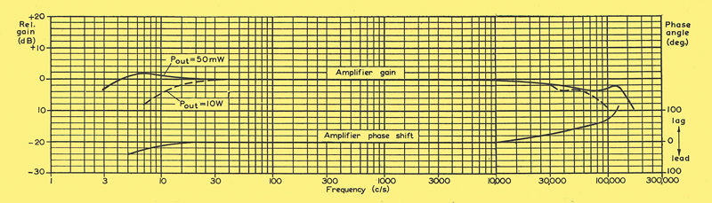
Frequency response and phase shift characteristics of 10W amplifier
The graph above shows the frequency response and phase shift characteristics of the basic amplifier (without tone controls). The response is flat to within 3dB from 3Hz to 60kHz at 50mW.
The power response (for 10W output) is also shown in the graph. This response is flat to within 3dB from 12Hz to 35kHz.
The loop-gain and loop phase-shift characteristics are given in the graph below.
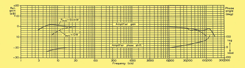
Loop gain and loop phase shift characteristics of 10W amplifier
Harmonic Distortion
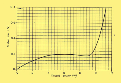
Total harmonic distortion plotted against output power for 10W amplifier
The total harmonic distortion, measured with an input signal at 1kHz, is plotted against output power and shown in the image above. The total harmonic distortion at an output power of 10W is less than 0.2%, a typical value being 0.15%.
Output Impedance
The output impedance of the amplifier measured at the 15Ω terminals is 1.4Ω for an output of 1W at 1kHz. This gives a damping factor of 10.7.
Tone-control Characteristics
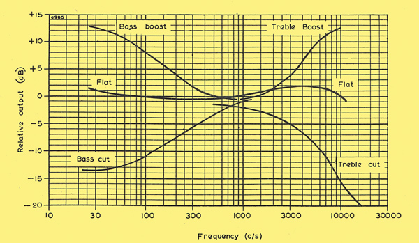
Tone control characteristics of 10W amplifier
The response characteristics of the tone-control circuits are shown. The ranges of control with respect to the response level at 1kHz are approximately:
- Bass: +12dB to -12dB at 30Hz
- Treble: +12dB to -12dB at 15kHz
Hum and Noise
The level of hum and noise in the prototype amplifier, measured with a short-circuited input, is typically 75dB below 10W.
Assembly of 10 Watt Amplifier
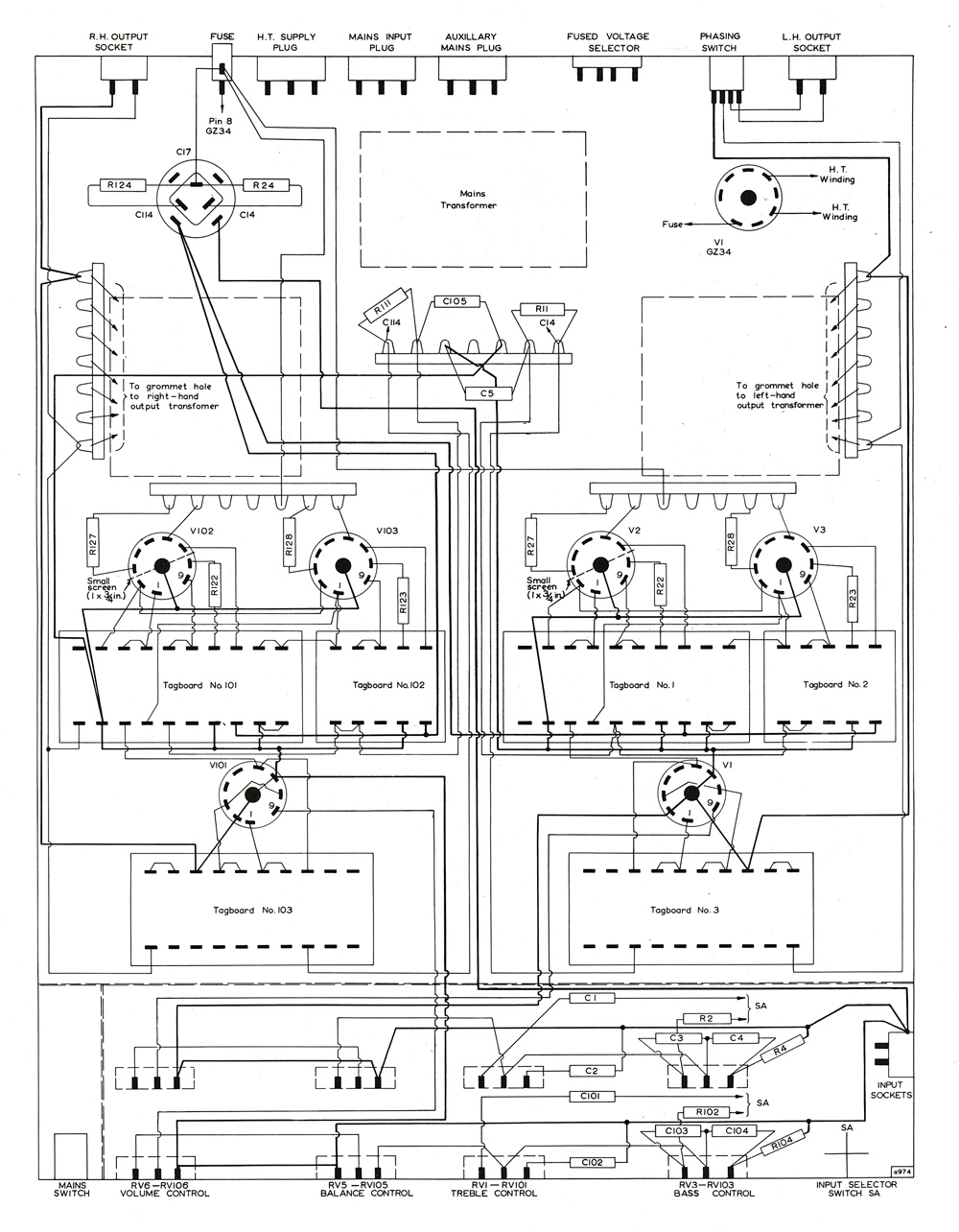
Layout diagram of 10W amplifier
Because of the high voltage gain of the ECL86, great care has to be taken in the layout of the amplifier. In particular every precaution must be taken to minimise stray capacitive coupling between the grid circuit of the triode section and the anode circuit of the pentode section of the ECL86.
The valve holders for the ECL86 should be nylon-loaded and skirted, and the spigots should be connected to the nearest earth point.
Since the wiring of the amplifier is critical, the use of printed-circuit boards is advocated, but if the wired version is to be made, strict adherence to the recommendations of the layout diagram above and the tag-board diagrams below is essential.
 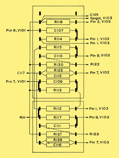
tag-boards Nos. 1, 2 (lh channel) tag-boards Nos. 101, 102 (rh channel)
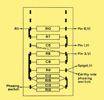 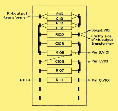
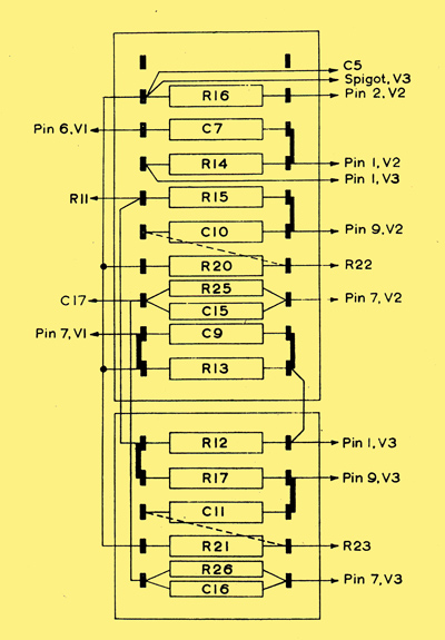
tag-board No. 3 (Lh channel) tag-board No. 103 (Rh channel)
Features of particular importance for ensuring stability, a low level of hum and minimum distortion in the wired version are:
The cathode resistor R9 of the EF86, the grid resistor of the triode sections of the ECL86, the decoupling capacitors C5 and C9 and the earthy lead of the feedback loop should all be returned to a common point in the wiring.
The cathode resistors R25 and R26 of the pentode sections of the ECL86 should be returned to the earthy point on the reservoir capacitor C17. The centre taps of the mains transformer secondary windings should also be taken to this point.
The earth lines of both channels should be kept separate, and should be connected to the chassis at one point only, preferably at the common input socket.
To ensure minimum capacitive coupling between the triode grid circuit and the pentode anode circuit, a small metal screen (about 1 x 0.75in.) is placed above the valve-holder for the first ECL86 between the input and output circuits, and soldered to the spigot.
Construction of 10 Watt Amplifier Chassis
Three versions of the amplifier are presented; two printed-circuit versions and one wired version. The power supply of the printed-circuit version forms a separate unit.
One printed-circuit version includes tone, volume and balance controls and thus forms a self-contained amplifier. In the other, the controls are omitted, and the version is thus suitable for use with the Mullard stereophonic preamplifier. The only other difference in the two printed-circuit versions is one of size: the version with controls is 1in. deeper. The wired version of the amplifier incorporates tone, volume and balance controls, and the power supply is situated on the main chassis.
The chassis for the printed circuit version or the wired 10W amplifier is made from separate pieces of 16 SWG aluminium sheet. The dimensions (in inches) of these pieces are:
Printed-circuit version with controls
- Main chassis 18 x 14.5 in.
- Large screen 14.875 x 2.188
- Small screen 2.188 x 1.938
- Cover plate 14.875 x 9.875
Without controls
- Main chassis 16.5 x 12.5
- Front panel 14 x 3
- Cover plate 14.875 x 9.875
Power unit
- Main chassis 8.5 x 7
Wired version
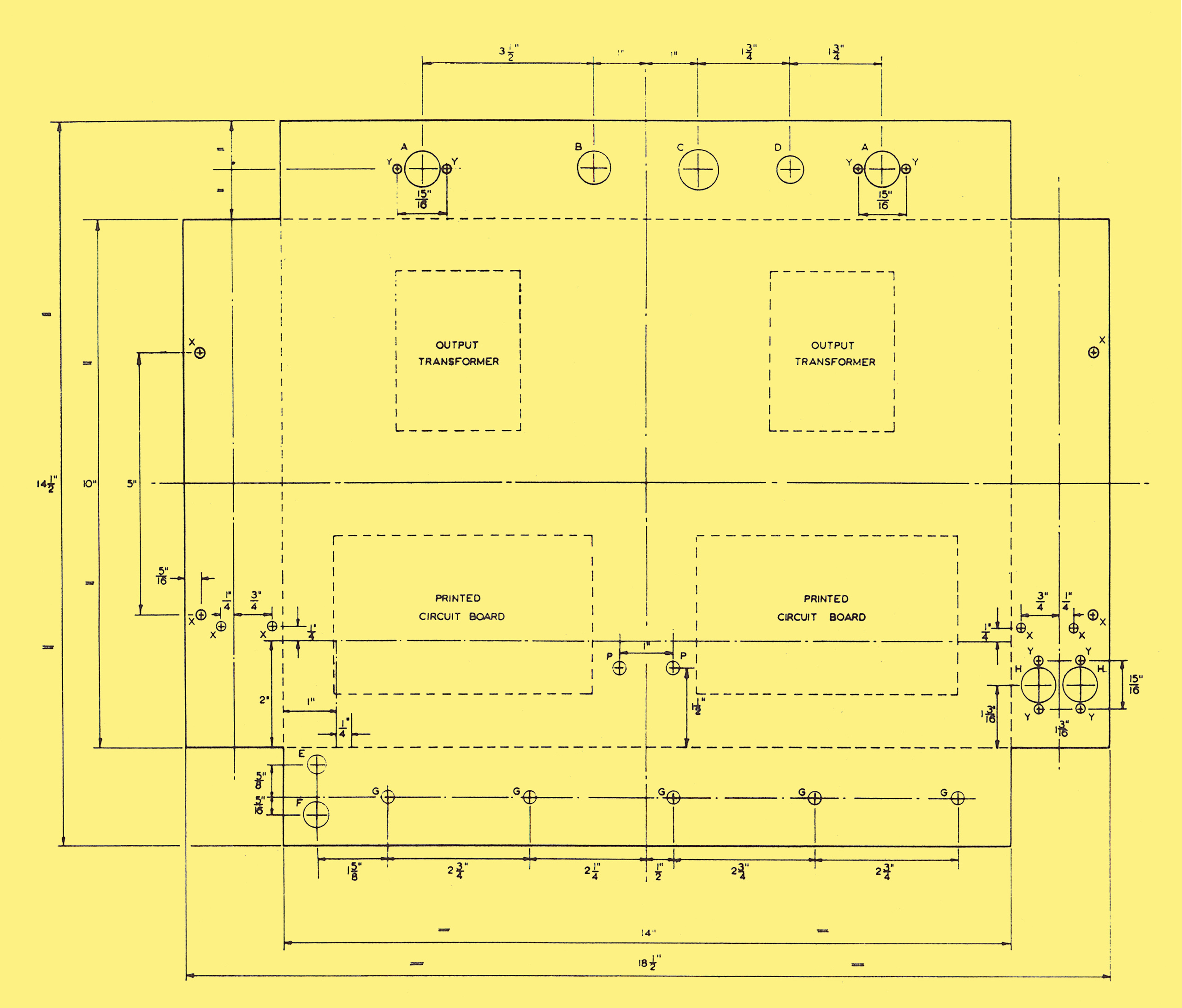
- Main chassis 18.5 x 14.5
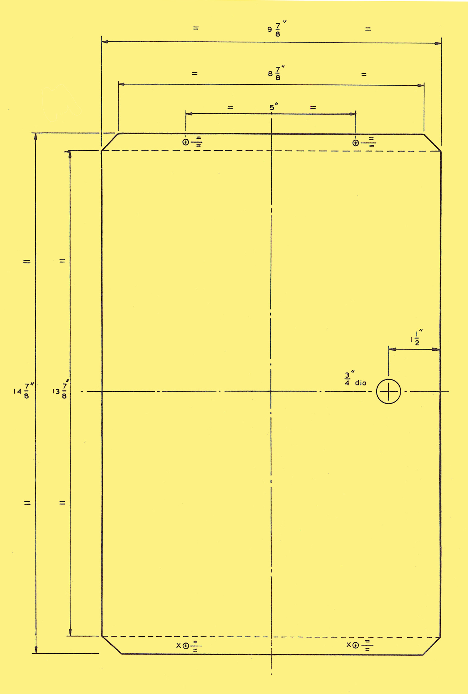
- Cover plate 13.875 x 10.875
- Large screen 10.875 x 2.188
- Small screen 2.188 x 1.938
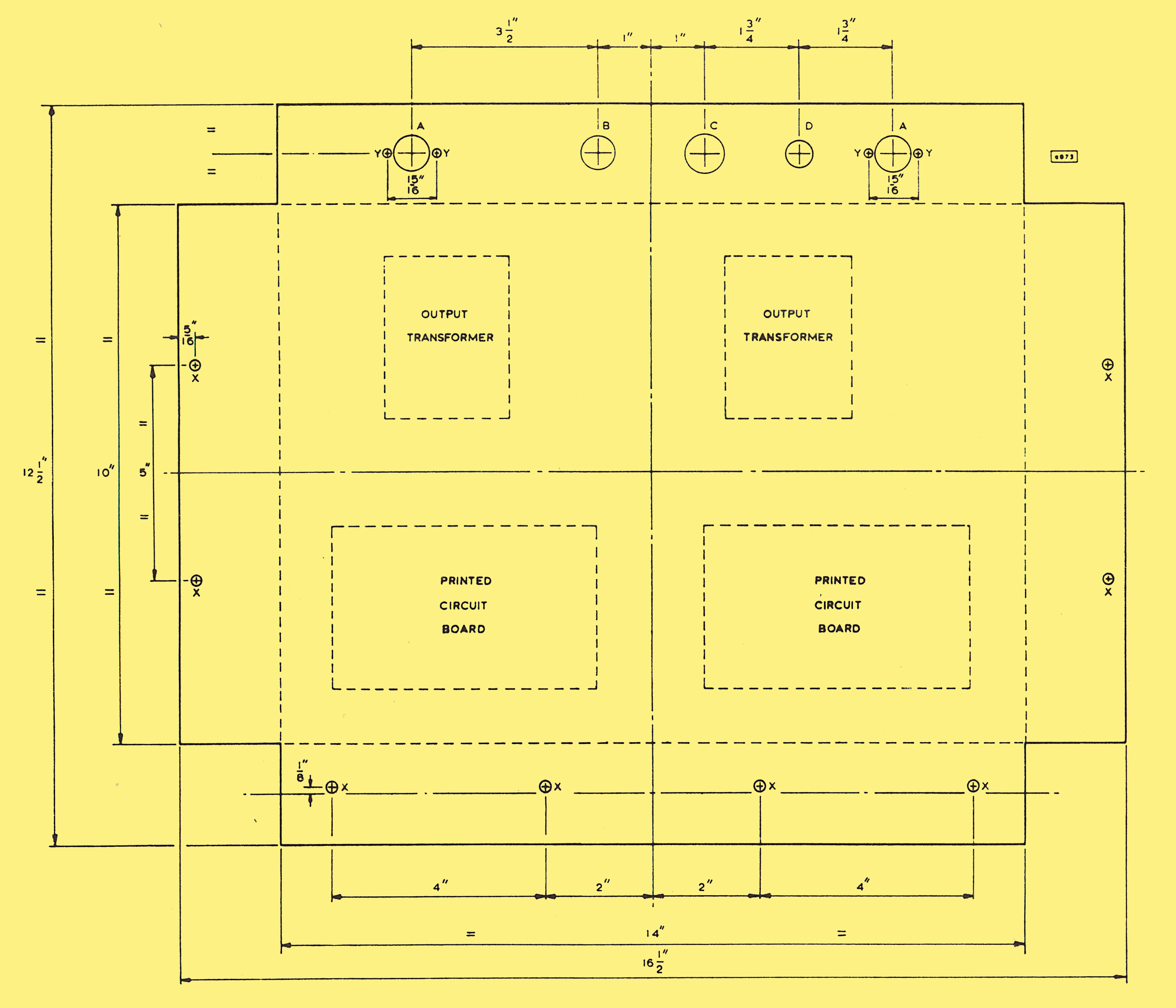
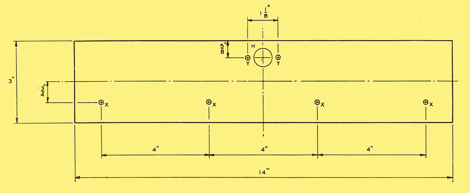
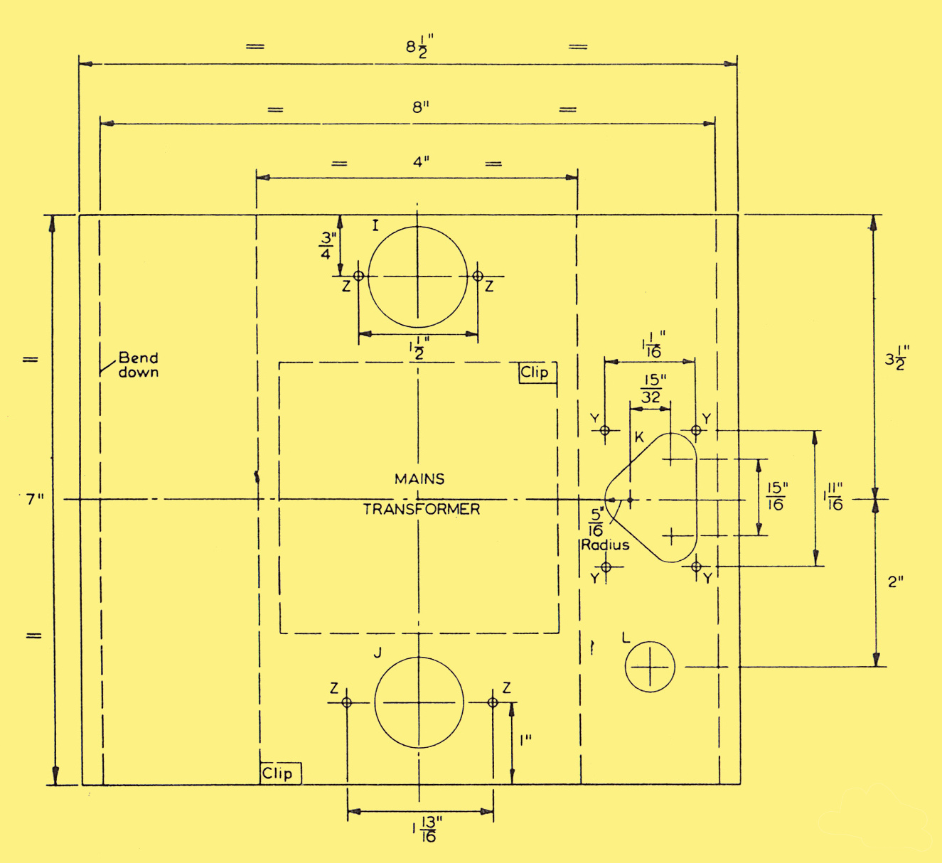
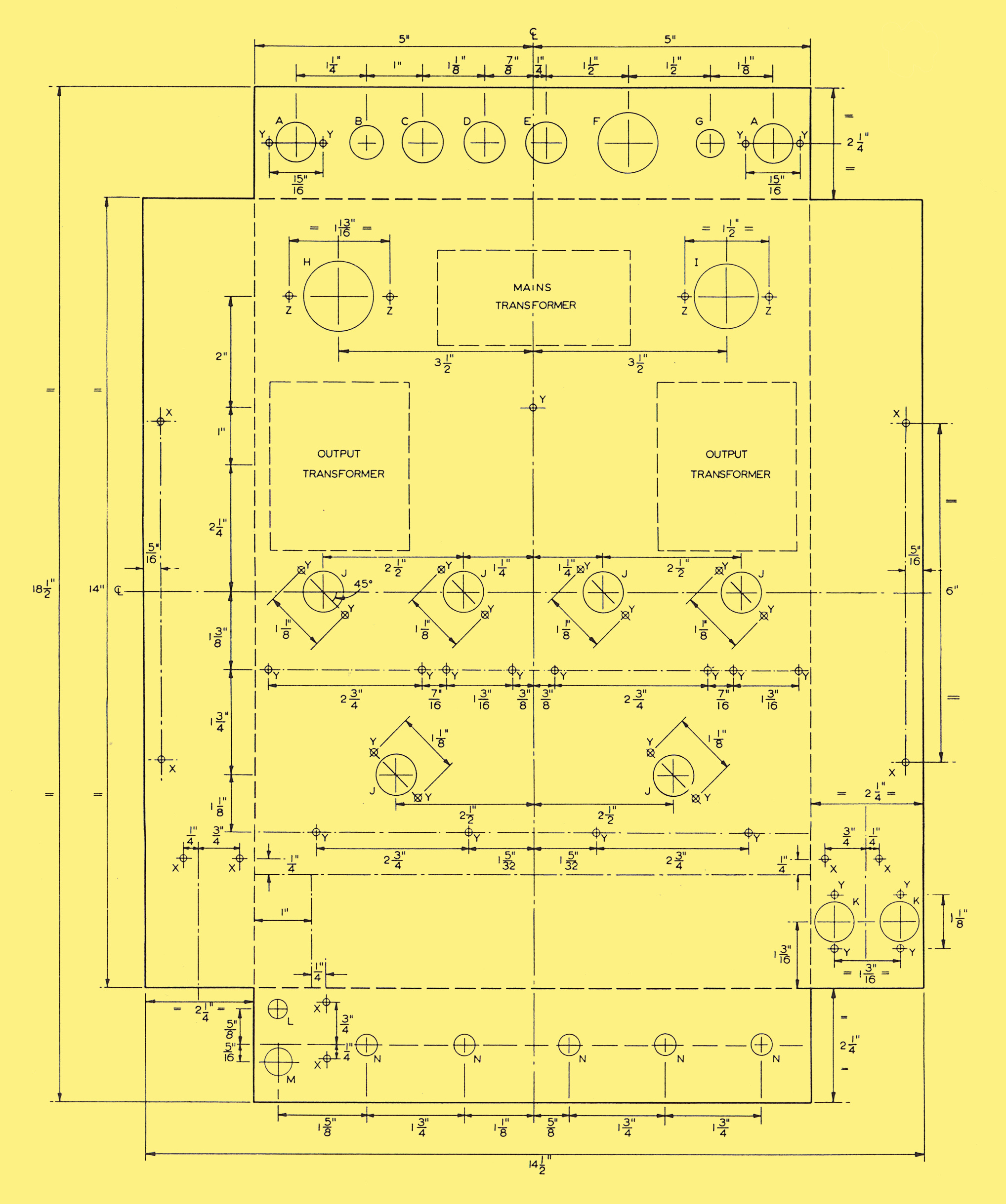
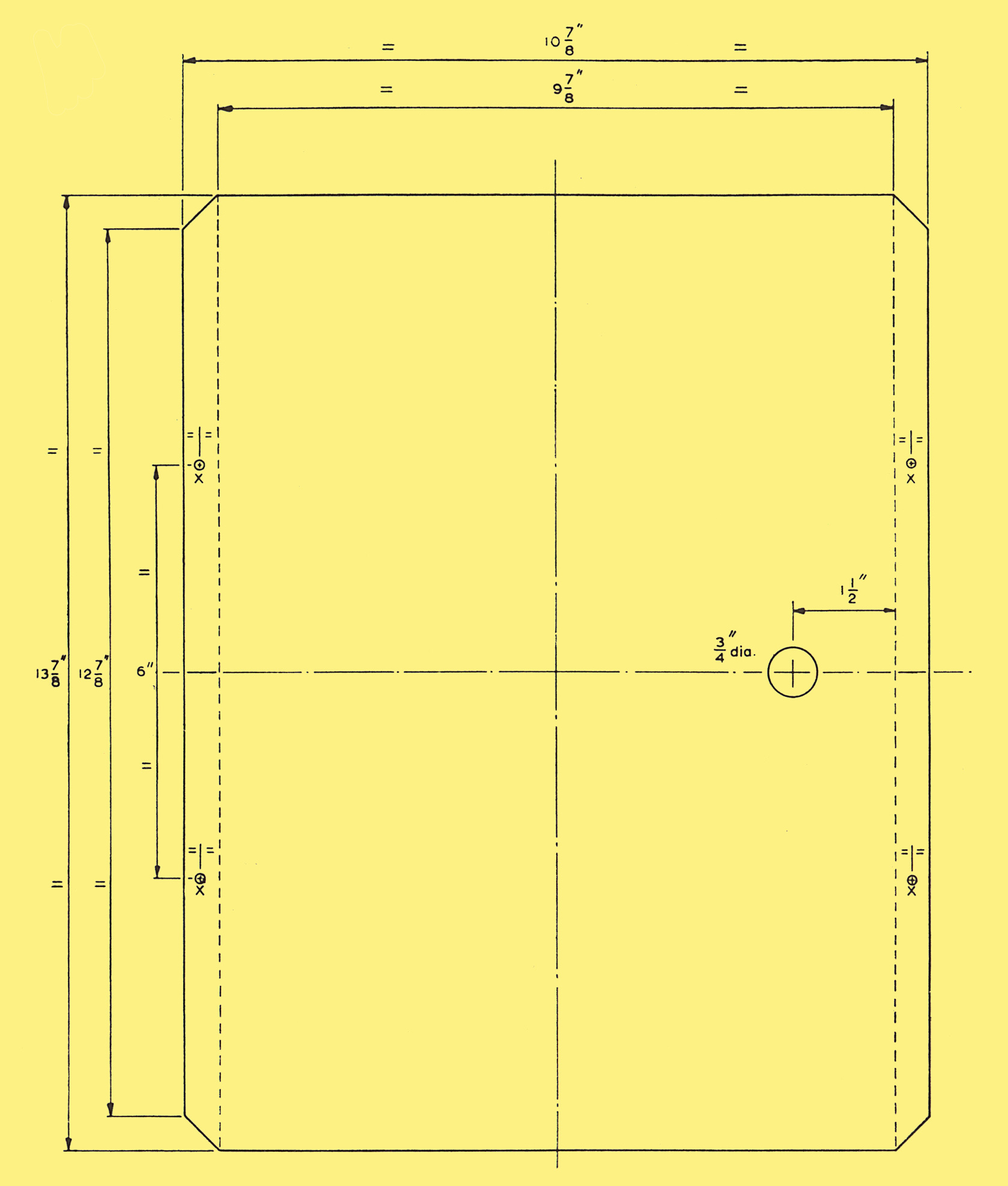
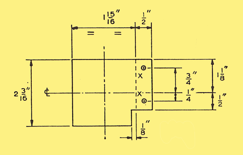
The diagrams below are for the printed circuit version. Each piece should be marked as shown. Bending at 90° is along the dotted lines unless otherwise informed. The holes should be cut as indicated. Please note that when clicking the images to see the full sized version the files are large.
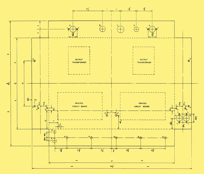
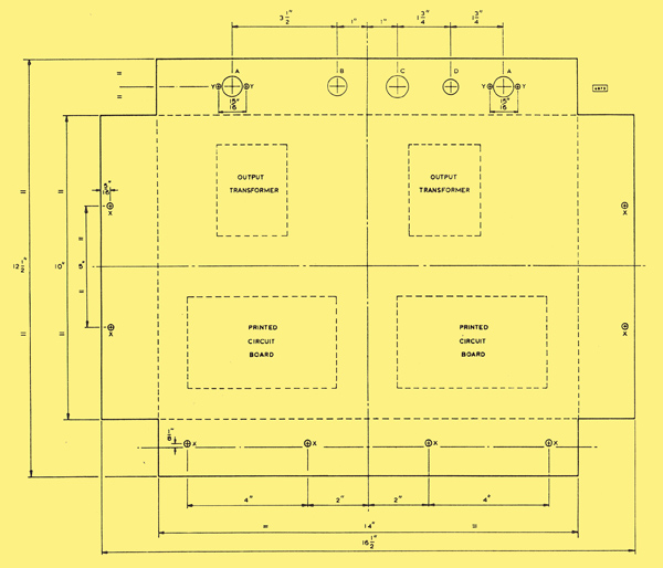
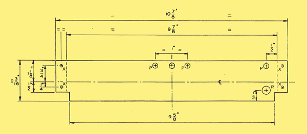
Main chassis (with controls)
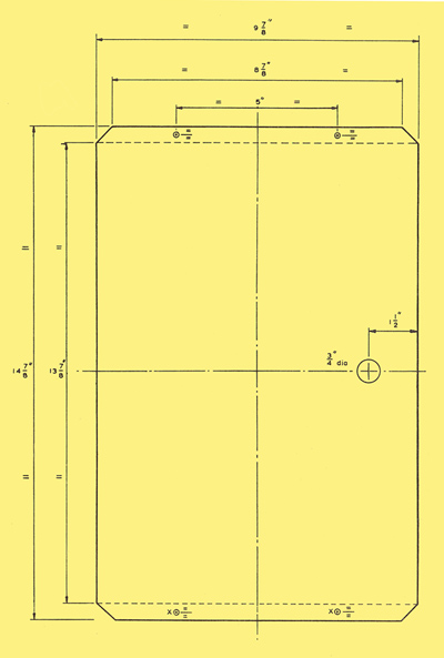
Base plate (with and without controls)
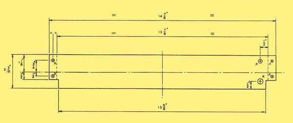
Large screen (with controls)
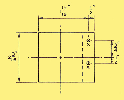
Small screen (with controls)
Main chassis (without controls)
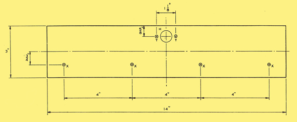
front panel (without controls)
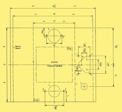
Power supply chassis (with and without controls)
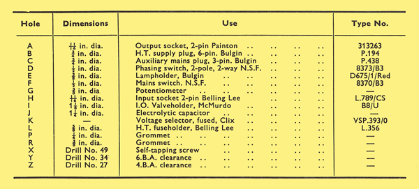
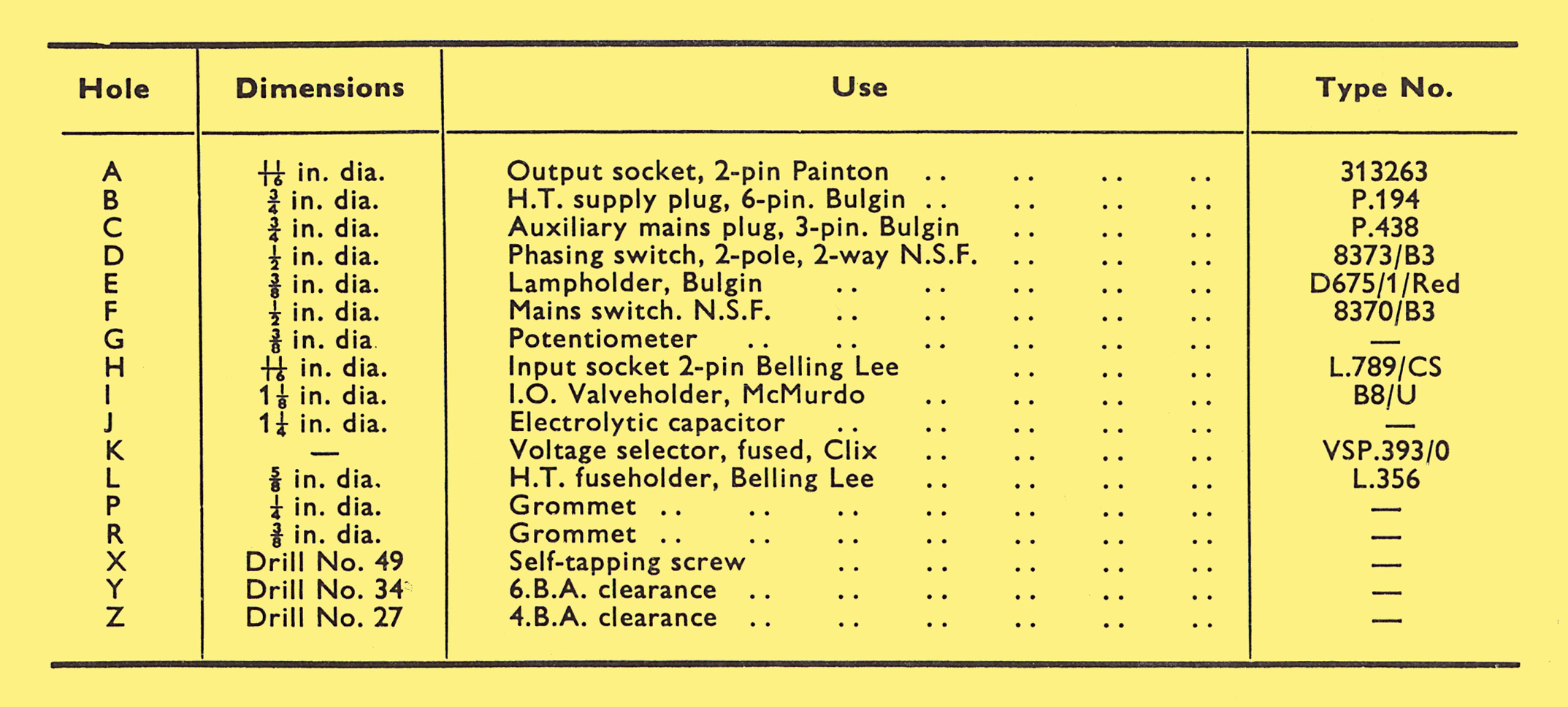
Key
The diagrams below are for the wired version. Each piece should be marked as shown. Bending at 90° is along the dotted lines unless otherwise informed. The holes should be cut as indicated.
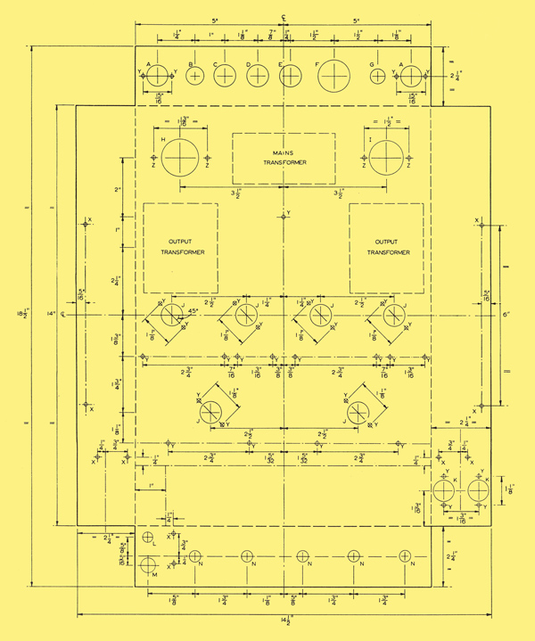
Main chassis
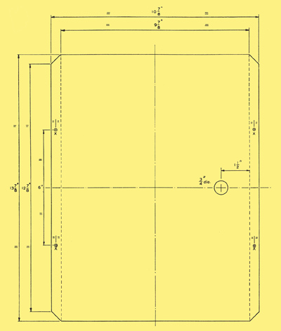
Base plate
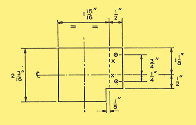
Small screen
Large screen
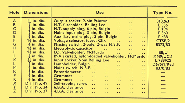
Key
|