|
Single ended Television Pentodes.
In several issues of The Wireless World there has been mentioned the possibility of shortening the wiring in a high frequency amplifier by using alternate top-grid and top-plate pentodes. Another attack on this same problem is represented by the latest American television pentodes, which are known as types RCA 1852 (6AC7) and RCA 1853 (6AB7). These both have metal shells, eight-pin octal bases, and heaters drawing 450 mA at 6.3 Volts; They differ only in that the 1852 has a steeper slope and sharper cut-off. All leads come through the base, the argument being that it is more important to shorten the wiring than to keep grid and plate on opposite faces of the metal baseplate of the amplifier. There is room for opinion on that point, but it is quite true that the pin arrangement has been chosen to shorten the wiring while permitting the shield can of the coupling device to serve the customary auxiliary purpose of screening each tube from its neighbour. The diagrams attempt to illustrate this and other points.
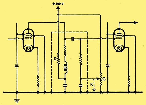
Fig. 1. Resistance coupled amplifier with sharp cut-off valve type 1852.
In a resistance-coupled VF amplifier the sharp-cut-off 1852 is suitable, used some what as inFig. 1. Two circuit conditions are here, suggested, In the first the grid resistor has a value not greater than 250 kΩ and is returned to chassis as indicated by the arrow K, the corresponding cathode resistor having a value of 160 Ω. The second condition applies to cases where it is necessary to employ a grid resistance as high as 1 megohm, with the consequent possibility of positive grid 'locking'. In this case the grid is first given a positive bias by returning the grid resistor as suggested by arrow C to a point about 9 kΩ from the chassis end of a 259 kΩ voltage divider whose 'high' end is 300 Volts (+) above chassis potential. This positive bias is then over balanced by increasing the cathode resistor to 1 kΩ. If for any reason the valve draws more than normal current, the overbalance increases and limits the rise. The screen supply (not shown) is through 60 kΩ from a 'plus 300' source; The heater has also been omitted for simplicity, two pins thus appearing blank. The anode circuit has been shown with the usual decoupler resistor D and a load composed of both inductance and resistance say, 2,500 Ω of the latter - merely as an illustrative example. Cathode by-passing, if used, has the usual effect of increasing gain and distortion.
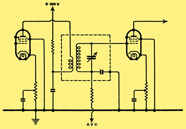
Fig. 2.This diagram shows the arrangement for transformer coupling with either the sharp cut-off or remote cut-off valve.
Short wiring. is also possible in a transformer-coupled stage, as shown by Fig. 2. In this case it is advisable to limit degeneration by partial by-passing of the cathode resistor. For the sharp-cut-off tube this resistor has a value of 160 Ω tapped for by-passing at 35 Ω from the cathode end, while for the remote-cut-off tube the values are 190 and 70 Ω respectively. The screen series resistor must be decreased from 60 kΩ to perhaps 30 kΩ if the remote-cut-off valve is used
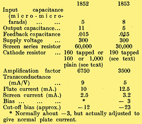
The foregoing operating suggestions are in part, and the following constants altogether, supplied by the manufacturer, the Radio Corporation of America.
|