|
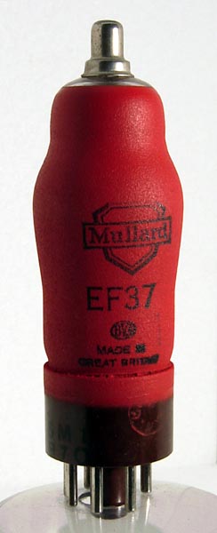
The EF37 as it should look.
Several boxes of valves were won in an Amateur Radio "Junk Sale" auction and at the bottom of one box was a broken EF37.
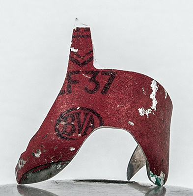
The valve was clearly a Mullard EF37 as this glass fragment shows.
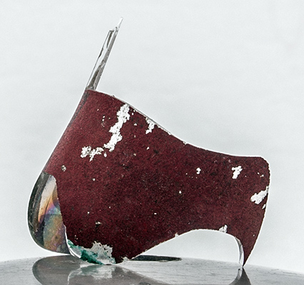
The glass thickness ranged from 0.63 to 0.75 mm on this small fragment. Viewed from outside the colour is the familiar Mullard red, however, looking through the inside of the glass the colour is a dull metallic light bronze.
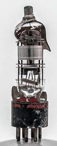
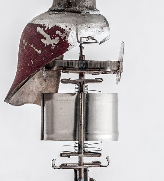
The complete valve as recovered. The envelope is missing and so is the spigot but the electrode assembly has not been disturbed.
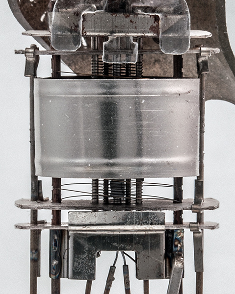
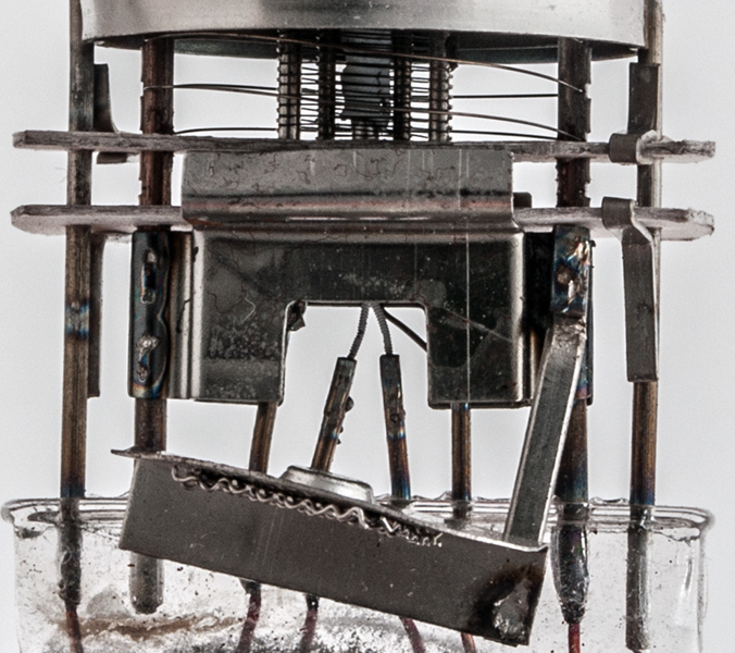
A face view of the main electrodes. Under the lower mica is a shield connected to the cathode and suppressor grid supports. This shield stops at a second mica sheet above which are the main components. The mica sheets have rounded ends and measure 21 x 8 mm. The anode is left bright in this low power pentode and is a cylinder 16 mm in diameter and 10 mm tall. The grid wires are held in place by the notch and peen system. A sharp roller cuts into the support rod, the wire is placed into the notch and finally a flat roller locks the wire in place.
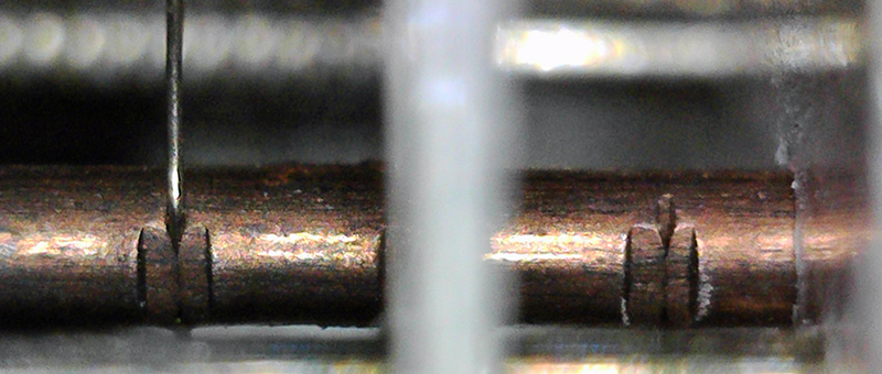
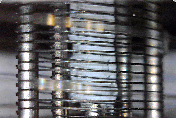
The microscope shows the details of the method. The image is of the suppressor grid near the base.
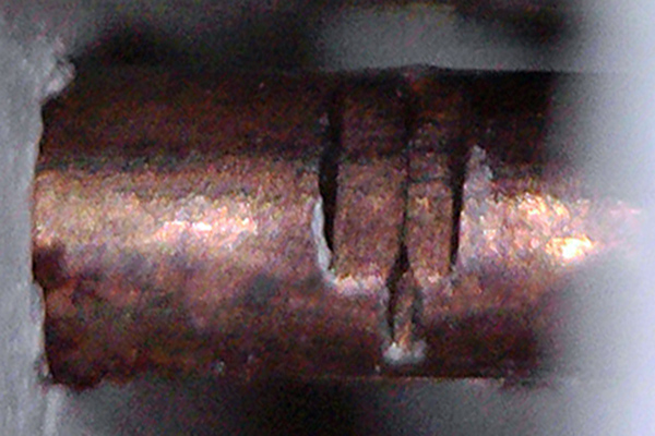
A closer view of the empty slot.
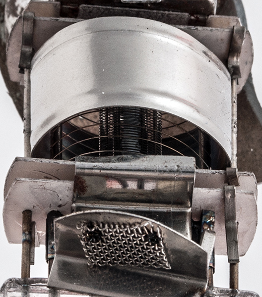
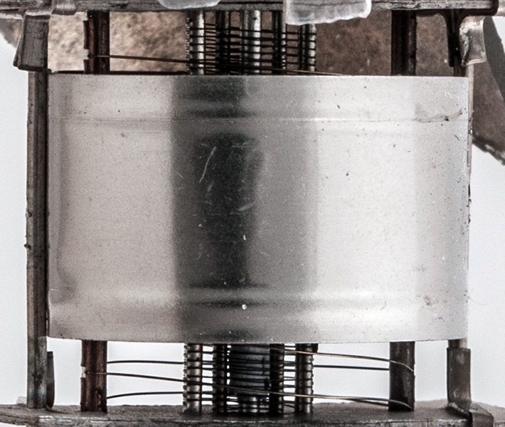
Here the valve is tilted away from the camera and the overall geometry of the electrodes becomes clear. The gauze at the bottom of the image was the getter holder.
This microscope shot of the grids shows the way they are wound. The control grid has a noticeable slope to the wire as the winding lathe's lead screw advances the supports. The break-up of the cathode coating will be due to the exposure to the air and moisture.
A side view of the main parts of the valve. This view is about five times life size as the mica sheets are eight mm wide. The suppressor grid is helical and eight mm in diameter. The screen grid is about 2.5 mm wide and the control grid is about one mm front to back.
The screen grid supports are 4.5 mm apart and the control grid supports are 2.5 mm apart.
The pinch and lower components including the shield and insulated heater. The latter looks to pass into the round cathode tube as a single loop.
|