|
Practically all modern television line output stages operate on the 'energy recovery' or 'resonant return' principle. In this operation a current in the deflector coil is caused to increase linearly with time. At the extreme limit of deflection a large current has been established in the coil and this current flowing through the coils inductance represents a high stored energy. During the flyback interval the coil performs half a cycle of free oscillation at a frequency determined by the capacity loading of the circuit. At the end of this interval the current in the coil is almost of the same magnitude as it was at the beginning but in the opposite direction. Since every effort is made to keep circuit losses small, the stored energy in the coil will be only slightly less than at the end of the scanning stroke. The coil voltage is then clamped by the efficiency diode and the current collapses linearly, transferring this stored energy to a large capacitor where it serves to 'boost' the HT line and in so doing, provides the first part of the next deflection stroke. (See for example Television Timebase Circuits, C H Banthorpe, Norman Price (Publishers) Ltd.).
In Great Britain, such circuits are usually operated with the pentode output valve behaving as a low resistance switch connecting the boosted supply potential to the inductance load. The pentode conducts for only part of the forward stroke, being switched on shortly before the current through the efficiency diode has collapsed to zero. The grid voltage is brought from a value well below cutoff to a point at which it is held by grid current and thereafter, for the remainder of the forward stroke, the grid exerts no control. Typical waveforms are shown below.
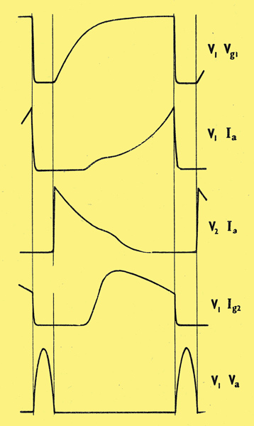
The pentode current builds up at very low-anode voltage, the working point rising up the 'knee front' of the Ia - Va characteristic. If the normal practice of using a fully decoupled screen resistor is followed this results in a constant screen voltage during the whole cycle. Thus if this screen voltage is high enough for the valve to pass the current at the end of scan, then when the valve is first switched on, with anode voltage and current practically zero, the screen current could be prohibitively high. This would result in the screen dissipation limit being exceeded with consequent deterioration of performance and probably life. In order to avoid this the screen decoupling condenser is omitted so that the screen voltage low at the start of pentode conduction and high at the end of the forward stroke when maximum anode current is required.
Under these conditions it is difficult to measure the screen wattage accurately. The most satisfactory method is to measure the screen current by means of two meters, one a normal moving coil milli-ammeter measuring the mean current IM and the other a thermal milli-ammeter measuring true RMS current IRMS The wattage dissipation in the screen is then given by-
Wg2 = VHT x IM - Rg2 x I2RMS
where VHT is the HT line supply voltage at the high potential end of the screen dropping resistor Rg2.
During the flyback interval the output valve is cut off to enable the current in the deflector coil to perform the half cycle of free oscillation referred to above. It is important that the valve should be completely cut off otherwise its anode impedance will damp the oscillation. This is more difficult than it may appear because, during flyback, there is a high positive peak voltage on the anode which modifies the cut off voltage in spite of the presence of the screen grid. A peak to peak drive voltage of at least 130 or 140 Volts is therefore usually required.
The rate of cut-off must be as fast as possible and the grid should be maintained at this extreme negative value until well after the positive maximum of the anode voltage. This is more easily achieved with a multivibrator type of drive circuit than with a blocking oscillator. Lack of attention to this point results in considerable variation of performance between valves and, usually, shortage of EHT.
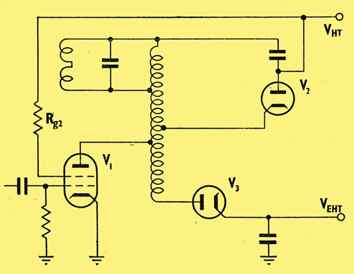
Basic line output stage with EHT generation.
|