|
Variable-μ Pentode
For a number of RF amplifier functions in receivers it is desirable to be able to control the gain of a pentode stage by varying its grid voltage. The required effect is that the stage gain should reduce as the control grid goes negative.

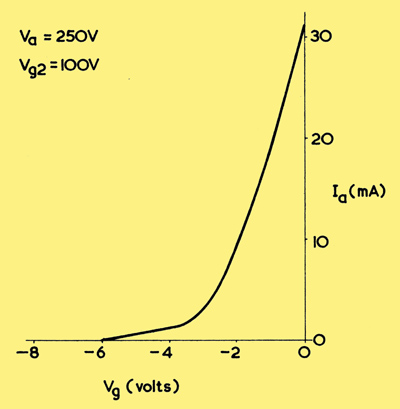
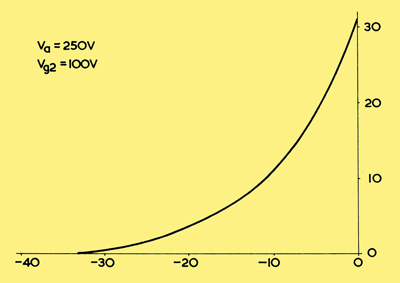
The diagram above shows an IaVg curve for a pentode which is not specifically intended for this class of operation. As may be seen, the anode current falls to zero at a grid voltage of -6 V, this being the cut-of voltage for the valve at the anode and screen-grid voltages indicated. By suitably spacing the wires in the control grid it is possible to obtain the IaVg characteristic illustrated below.

This characteristic shows a continual curvature throughout its length and the cut-off voltage is reached at -33 V. This curve is representative of a variable-mu (or variable-μ) RF pentode, and it demonstrates the fact that the mutual conductance of the associated pentode may be adjusted 'smoothly' by varying the control grid voltage. With the first curve, changes in mutual conductance are liable to be more abrupt as cut-off point is approached.
The variable-mu effect is obtained by variations in the spacing between the control grid wires along the length of the control grid assembly. In a typical assembly the wires at each end may be closely spaced, the spacing increasing towards the centre so that the centre wires are proportionately widely spaced apart. When an alternating signal voltage is applied to the grid, the consequent control over electrons reaching the anode decreases as the grid wire spacing increases. Thus, with the grid assembly just mentioned, greatest control at low negative grid voltages is exerted by the closely spaced wires at the end. At high negative grid voltages the electrons from the cathode will not pass through the closely spaced wires at the end of the grid structure, and will only pass through the widely spaced wires at the centre, where less control is exerted.
Although the type of valve under discussion is known as a variable-μ. valve, it is more helpful to think in terms of the changes in mutual conductance which occur when the control grid voltage is varied.
|