|
Type Q. As far as we know this classic landmark valve was the first 'hard' (i.e. high vacuum) wireless receiving valve to be designed in Britain. The 'French TM' type (1915) was earlier but was not of British design and was not initially manufactured here. 'French' receiving valves made in the UK to a British specification were designated Type R. (Note that R comes immediately after Q.) We reckon that the Q and R types both date from mid-1916 but have to admit that the whole business of dating WWI types is full of guesswork based on incomplete and somewhat conflicting evidence.
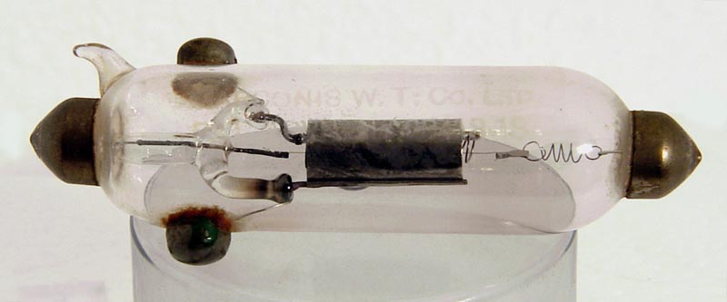
The Type Q was designed by Captain Round as a general-purpose receiving valve for the Marconi Company (then MWTCo.) Its key features are small size (it is known that Round had airborne applications in mind), well-spaced electrodes (to minimise grid/anode capacitance so that the valve would be capable of HF amplification), and total enclosure of the filament by the grid assembly. This last feature was in accordance with one of Round's patented design principles used on his previous 'soft' (ie gas-filled) receiving valves. Round's last design of receiving valve had been the Type N (1915?) Careful comparison of the Type Q with the type N shows interesting similarities as well as obvious differences. The extent to which Round was consciously trying not to imitate patented features of the 'French' is not clear.
Early production of the Type Q was by Ediswan (as for Type N). However, somewhere around 1919 manufacture of the Q (but not the N) was transferred to MOV. All the Qs seen look pretty similar and we suspect they may all be later samples made by MOV.
Type Q was a bright triode with a Tungsten filament rated at around 5V, 0.5 A (data sources vary). As with his soft valves, Round packed a lot of performance into a small space so the gain was exceptionally high (μ = 45, gm = 0.3 mA/V) for its time. Type R had μ = 9, gm = 0.225. The penalty for this high gain was high Ra (150,000 ohms) and the consequent necessity of using a high anode voltage supply (150 to 200 Volts), which was logistically a disadvantage.
Captain Round's Type Q of 1915/16 was an excellent valve for professional use but for military and Merchant Navy purposes it had two main drawbacks: 1) It was a high impedance valve requiring at least 150 V HT for good performance. Suitable spare HT batteries were not always available on the slow boat to China and 2) It was a high-gain valve and required skilful use for HF amplification without undesired self-oscillation.
Professionals had the necessary skills but soldiers and matelots did not.
Captain Round therefore redesigned the valve on the lines of the type R but with a much smaller anode diameter and a more open grid. The result was a valve of relatively low impedance which could operate satisfactorily from 24 V HT. Since almost all ships worthy of carrying Wireless during WWI had 24 VDC main or emergency lighting systems, this meant that the slow boat to China now didn't need an HT battery at all.
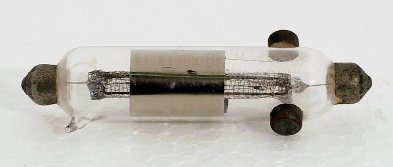
The high anode impedance and low anode capacity of the type Q made it particularly suitable for sharply-tuned HF amplification. By contrast the much lower anode impedance of the type V24 provided parallel damping on the output circuit so that tuning was woolly and the gain was much lower. V24's were therefore used in multi-valve strings coupled by means of untuned (aperiodic) HF transformers. It therefore took 3 or 4 V24's to provide the RF gain formerly provided by a single type Q but the set was much tamer and easier to use without self-oscillation.
In professional hands the Type V24 was capable of operation up to extremely high frequencies and, during the 1930s, was used as an oscillator at centimetric wavelengths. V24's remained in the lists well into the 1940s and were held in stock by Marconi International Marine well into the 1960s.
During WWI the Marconi Company made a number of voice transceiving sets incorporating type Q valves. Technical details of some of these sets survive. It is interesting that the accompanying transmitting valve was usually a type S which was derived from a French prototype although made in the UK. It is even more interesting to see how the designer of the receiving section has had to solve awkward problems due to the high Ra value of the Type Q. One gets the impression that a Type V24 would have been used instead of a Q in some positions, had it been available at the time. We take this as evidence that the Type V24 did not become available until at least a year later than the Type Q.
Type Q valves survive in surprising numbers most of which look unused and seem to be in good working order. Has anyone seen a well-used (blackened) Type Q? Many specimens work well on a tester. We have been told that Qs could be used successfully as low-power transmitters with up to 400V on the anode.
MOV did not like making the Type Q (it was too fiddly for mass-production by low-paid factory girls). They therefore redesigned it to be identical to the Type V24, except for grid pitch which was tighter. The modified Q was designated Type QX and had mu and Ra values around half the Q's values. However, the QX worked well at lower anode voltage and proved a better complement to the V24 in (later) receivers using both types. Unlike Qs, good working QXs are very scarce!
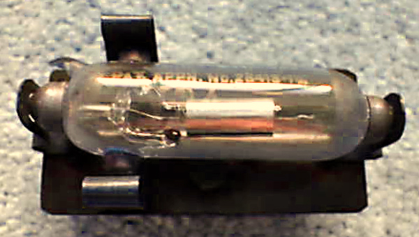
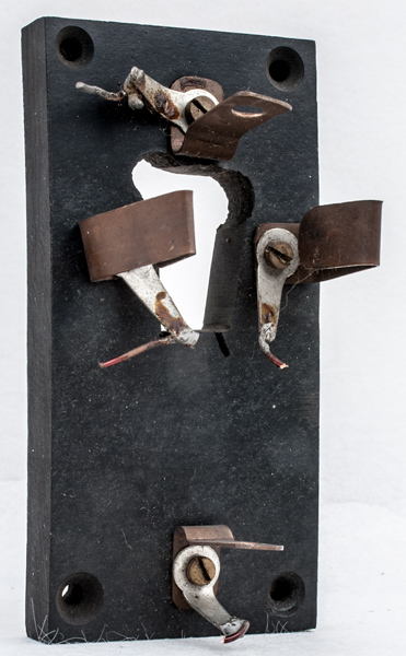
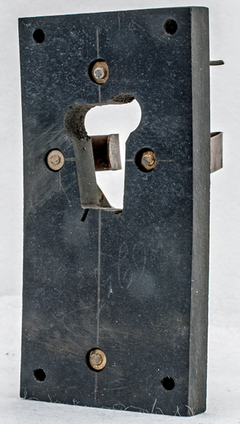
A V24 in its valve holder
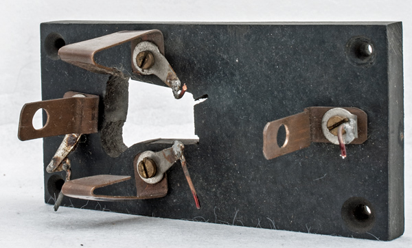
Below is an example of a home-made ebonite base for the V24. The base measures 50 x 100 mm and is 10 mm thick. The base has bowed with age. The length of the connections seems to negate the advantage of the low inductance leads inside the valve.
|