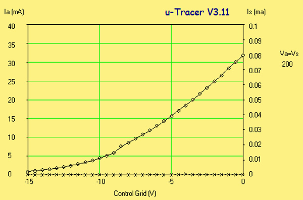
This exhibit has lost its identification but visually and dimensionally matches the 41MHL. The problem comes when placed on test as the curve shows a greater anode current than the 41MHL.
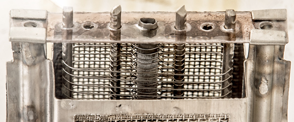
The 41MHL (see parameters above) is an indirectly heated triode and was suitable for detector or audio amplifier in a radio receiver. Internally the valve has both a control grid and a screen grid. The latter is internally connected to the anode by a length of coiled wire.
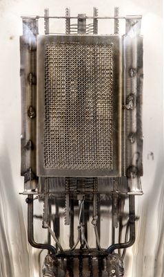
The box anode.
The anode is a complex arrangement with about 32 spot welds.
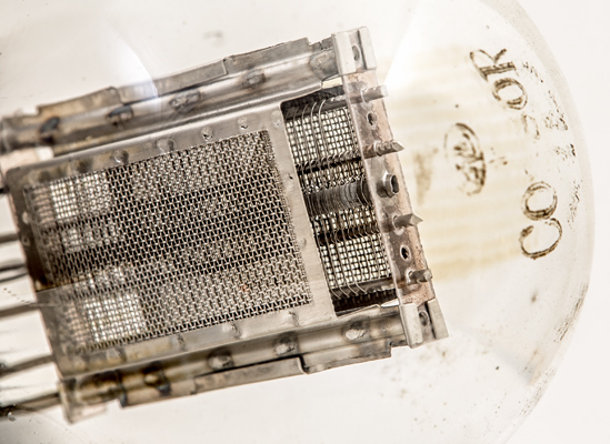
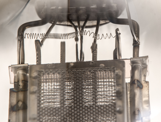
The whole electrode arrangement.
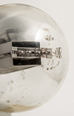
The dome carries the Cossor name, BVA logo, Made in England and code V8.
The top mica is held in folds of the anode side walls. The screen grid wires pass flat from side to side. The control grid is shaped to fit round the cathode.
The control grid wire looks to have been crimped around a central rod to give the precise shape round the cathode tube.
Why have a second grid? Is it a design feature or a way to use an existing tetrode design back as a triode. The second grid is connected to the anode by the length of coiled wire.
μTracer 3 plot shows a significant total anode current with a 200 Volt HT.
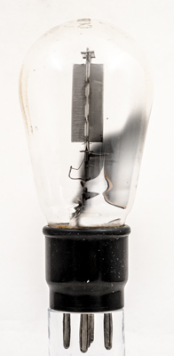
The balloon envelope is 54 mm in diameter, and excluding the B5 base pins is 113 mm tall.
References: Data-sheet, 1043, 3002 & 1040. Type 41MHL was first introduced in 1930. See also1930 adverts.