|
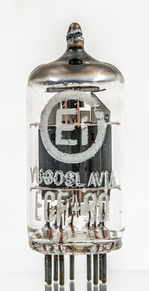
ECF80Sensibly equivalent¶ to:See also:
|
|
|
|
The ECF80 was designed for operation as a frequency changer up to 220 MHz. As 1950s television receivers tended to use the PCFnn 300 mA valves, the production of this valve with a 6.3 Volt heater suggests that it was aimed at the professional VHF communications market.The triode is the oscillator and has to produce 5 V pk-pk signal. The screened pentode is the mixer. The valve has two cathodes so two independent valves are sited in the one envelope.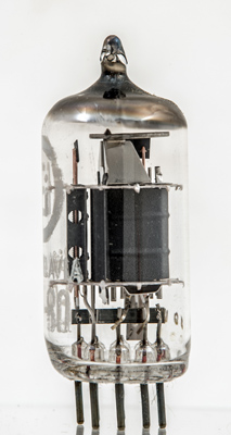
The triode on the left has extended copper grid supports with heat dissipating fins at the top. The pentode also has copper supports for the control grid and is topped with radiating fins - blackened for efficiency.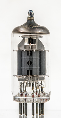
The pentode is mounted at right angles to the triode. Through the hole in the anode wall can be seen the suppressor grid support.The thin glass tube envelope is 20 mm in diameter and, excluding the B9A base pins, is 48 mm tall.References: Data-sheet & 1040 Type ECF80 was first introduced in 1954. See also 1954 adverts. |
Pin Connections
| 1 | 2 | 3 | 4 | 5 | 6 | 7 | 8 | 9 |  a(t) | g1 | g2 | h | h | a | k,s,g3 | k(t) | g1(t) |
|
|
Absolute Maximum Operating Conditions
| Vh | Ah | Va | Vs | Vg | mAa | mAs | ra | gm | 
| 6.3 | 0.43 | 250 | 180 | -5.8 | 5.7 | 1.4 | 1.5M | 2.1 |
|
Absolute Maximum Operating Conditions
| Va | Vg | mAa | ra | gm |
| 100 | -2 | 14 | 4K | 5 |
|
PDF scanned from an original document held by the museum |
Updated January 24, 2023.
|
|