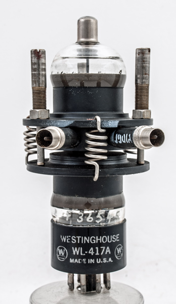
This is a type 417A reflex klystron with a 'WL' prefix. The 'WL' prefix indicates the manufacturer. Small klystrons of this class were widely used as local oscillators in radar receivers. The 417A was used in the Radio Set AN/CPN-3.
The 417A was designed to operate at 2.65 to 3.33 GHz and generate 250 mW of RF. The cavity is integral to the design and the tuning is mechanical. The RF connectors can be seen to be co-axial.
They were normally tunable over a modest range and were adjusted to be exactly in tune with the (much more powerful) pulse transmitting valve (usually a cavity magnetron). The magnetron generated an RF output only briefly, when pulsed, but the klystron provided a continuous low-level RF signal which could be used to 'beat' (mix) with the faint echo signals in order to reveal small frequency differences of Doppler shifted echoes from moving aircraft.
The type 417A was from fairly early in WWII but this specimen looks to have been made post-war.
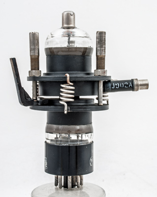
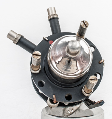
The repeller connection is the top cap. The cavity is held in tension by powerful springs. The adjustment screws are slotted and fixed with the locking nuts.
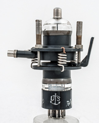
The anchor and US indicates a product for the American Navy. The bracket on the right is for fixing. The underside of the cavity is corrugated disc of thin metal that allows a small degree of movement.
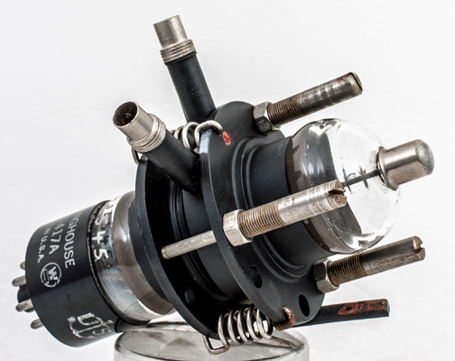
The twin coaxial outputs with screw threads to retain the connectors.
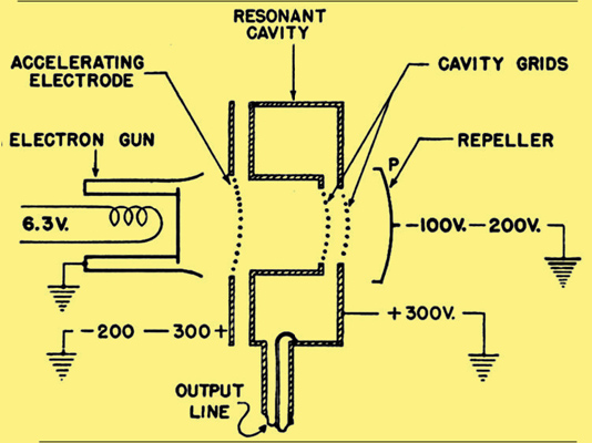
This diagram shows the electrode system of a reflex klystron structure. The repeller electrode directs the electrons back towards the cathode. The cavity with gap acting as buncher for electrons coming from the electron gun and as catcher for electrons pushed back by the repeller. Bunching occurs along the way from the cavity to the vicinity of the repeller and back.
Top view showing the repeller disc and the three adjusting screws.
The wide metal tube envelope is 33 mm in diameter and, excluding the IO base pins, is 111 mm tall.
References: Data-sheet, Private communication & 3002.