The Taylor tubes were American transmitting valves built for reliability. They were conservatively rated for a long life. This valve was designed for use up into the low VHF region at 60 MHz. The ratings given in the data-sheet are for both CW and phone. For AM service as a class C amplifier the output was 38 Watts, for CW use the power rose to 44 Watts. The peak grid current was 25 mA fully driven. With an amplification factor of 20, a drive level of 3.6 W was specified for full output.
The TZ20 was designed as a zero bias Class B modulator.
In 1938 Ediswan introduced the ESW20, said to be a T20 replacement.
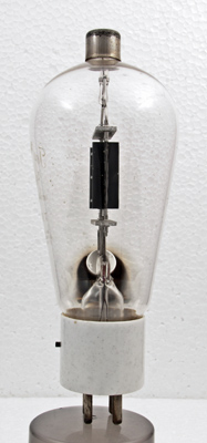
The side view of the box anode. The base is ceramic for low RF loss at high voltage and/or humidity.
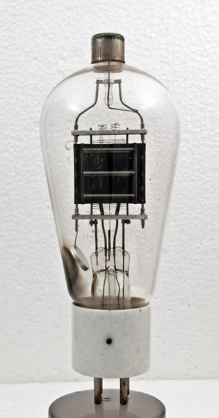
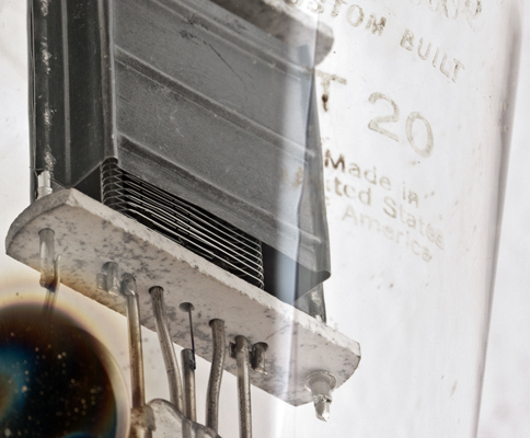
The T20 is directly heated. This view shows the getter holder near the pinch, the box abode and the shaped grid winding. The etched Type designation is also visible. The wording below T20 is Made in The United States of America.
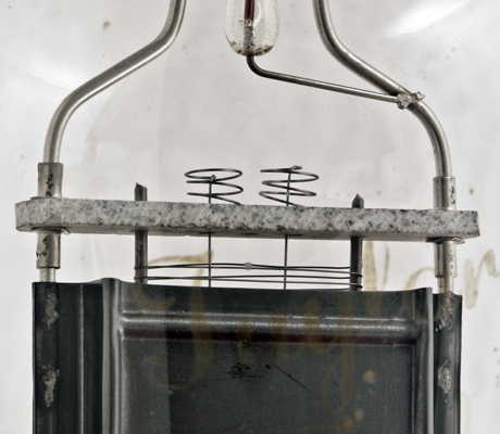
The top ceramic support. The anode wire passes through a glass rod that the anode supports clamp round. The two filament tension springs indicate that the filament passed through the valve four times.
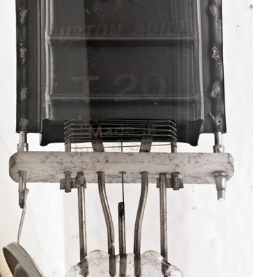
The lower ceramic support. The filament can be seen inside the grid winding. The envelope lettering is faint but can just be read.
The classic envelope is 60 mm in diameter and, excluding the UX4 base pins, is 142 mm tall.