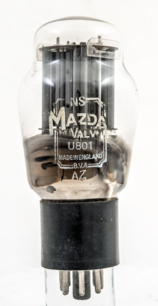
The U801 is a television HT rectifier. The rating is given as 1,500 Volts PIV. The unusual feature is the fact that the construction is as a pair of full wave rectifiers within the envelope. The general belief is that the U801 with its very high heater rating was unreliable due to the fragile heater. Additionally it seems to have been prone to shorting out.
The above comments look like an understatement. John makes the following detailed comments:
It was designed as a television HT rectifier for universal or AC/DC receivers. The four anodes were supplied each with a 100 ohm surge limiter resistor and this caused problems. One would go open circuit putting the HT load across the three remaining anodes to produce a run away fault with final destruction of the valve and all remaining limiters in a mass of sparks!
Its heater was very bright and warmed up VERY quickly. I looked as if it was about to fail when working normally.
Some makers used two anodes strapped together as an HT rectifier and the other two strapped as the efficiency diode. This caused an even more spectacular failure rate.
Ekco, Murphy, Ultra and many others used it but the failure rate was so high that they went to Mullard, a sin if you were contracted to Mazda, to supply PZ30 or a pair of PY82's to take care of the HT supply. The Mullard valves never failed. It also prompted set makers to use selenium solid state rectifiers.
The U801 was employed from around 1951 to 1953. Mazda had great difficulty producing rectifier valves around this time. They all had flaking cathodes and usually ended in a firework display. U22 - U25 U801 U281 U282 and others all suffered from this problem. They never managed to manufacture a half decent television HT rectifier resulting in makers contracted to Mazda to use finned HT rectifiers until they produced the PY32/PY33 under license from Mullard in the mid 1950's.
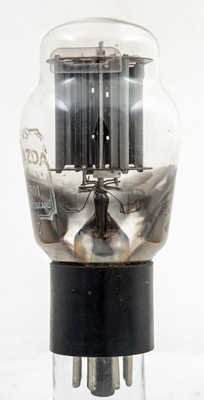
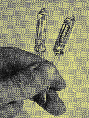
The four sections arranged in a pair of T formations with the line of one anode pointing to the cathode of the next.
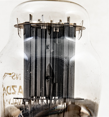
A closer view: the cathode is near the centre with the heat radiating fins facing the outside.
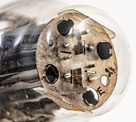
The four round cathode tubes seen from the top. Each anode is shaped with a cylindrical end section.
The classic envelope is 54 mm in diameter, and excluding the IO base pins is 110 mm tall.
References: Private communication & 1040. Type U801 was first introduced in 1950. See also1950 adverts.
