The UCC84 and PCC84 double triodes differ only in heater requirements. Both were developed to meet the needs of VHF broadcast reception.
The UCC84 was specifically designed for cascode operation. The normal configuration was for triode one to be operated as a grounded cathode stage directly coupled to triode two. Triode two was connected as a grounded grid stage.
Most televisions used series heater chains at 300 mA consumption but small sets with fewer valves used the 100 mA series valves.
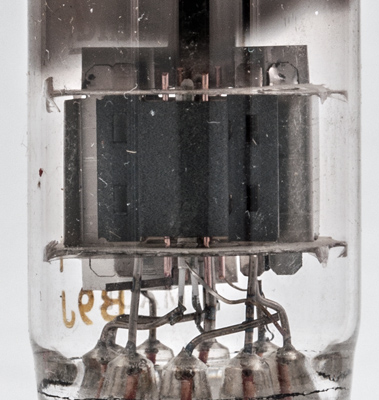
The screening for the left triode, grounded grid stage, differs from that of the right hand triode.
The control grid is wound on copper rods and the anode is shaped to bring the working face close to the grid but keep the main material away from the grid area.
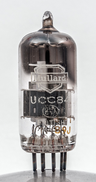
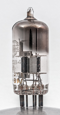
The thin glass tube envelope is 20 mm in diameter and, excluding the B9A base pins, is 48 mm tall.
References: Data-sheet & 1040. Type UCC84 was first introduced in 1954. See also1954 adverts.