|
PD500Sensibly equivalent¶ to:9ED4See also:
|
|
|
|
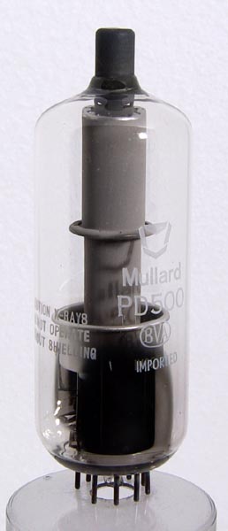
Mullard describe the PD500 as a shunt stabiliser triode for colour television receivers.Regulation of the EHT voltage it makes the picture stable in both geometry and intensity. Stabilised HT voltages had been used on professional display equipment such as oscilloscopes for many years.The same rectifier but with a 6.3 Volt heater is the ED500.The dissipation is high because of the very high anode voltage and the fact that with low picture intensity most of the EHT is dissipated in the regulator. Under such conditions, where the intensity had been turned down, the anode could glow cherry red.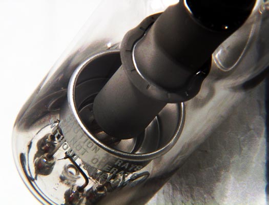
The heater, cathode and grid structure are at the bottom of the valve and lie horizontally, i.e. in a plane parallel to the base disc. The bright electrode is the screen and the anode is the grey cylinder connected to the top cap. A warning on the envelope says that x-rays are produced during operation, and that the valve is to be used with a shield.Simon Pearson has first hand knowledge of the PD500 and its use in British colour television receivers. The PD500 would have been connected between the cathode of the GY501 EHT rectifier and chassis. The grid of the PD500 was connected to a servo circuit and the valve operated to keep the EHT voltage reasonably constant.The wide glass tube envelope is 36 mm in diameter and, excluding the B9D base pins, is 102 mm tall.References: Data-sheet & private communication. Type PD500 was first introduced in 1966. See also 1966 adverts. |
Pin Connections
| 1 | 2 | 3 | 4 | 5 | 6 | 7 | 8 | 9 | tc |  k | s | nc | h | h | nc | nc | g1 | nc | a |
|
|
Absolute Maximum Operating Conditions
| Vh | Ah | Va | mAa | Pdiss | 
| 7.3 | 0.3 | 25,000 | 1.6 | 30W |
|
Updated January 06, 2022.
|
|