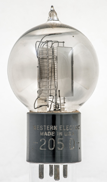
The Western Electric 205D was designed for either audio or RF amplification. The maximum anode dissipation is 10 Watts and construction follows the pattern of other WE telephone valves with a vertical glass rod as the main support but a wound grid replaces the earlier ladder grids.
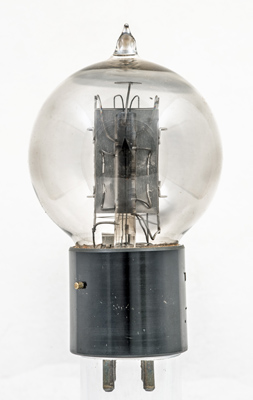
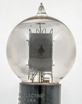
The locating pin for the bayonet base is on the left. The main glass rod support attaches to the stem of the tube that forms the pinch at the top.
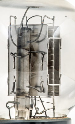
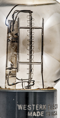
Here the support wires can be seen embedded into the glass support.
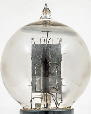
The flat plates of the anode are joined with U shaped wires. The wire going upwards leads to the getter holder and the inside of the envelope is silvered by the gettering.
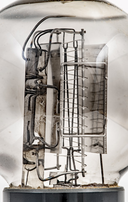
The M shaped ribbon filament with the wound grid passing close the the ribbon. the anodes are some distance away.
The grid construction: wires are horizontal where they have been notched to the support and after the correct spacing they slope down to the next fixing point passing flat across the filament.
The second plate anode furthest away from the glass rod.
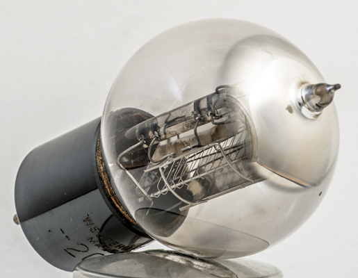
Oblique view and a clear image of the circle of gettering at the top.
The balloon envelope is 58 mm in diameter and, excluding the base pins, is 98 mm tall.
References: Data-sheet. Type 205D was first introduced in 1924. See also1924 adverts.