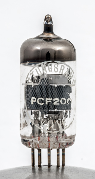
The PCF200 was designed for use in multiple stages of a television receiver.
The expanded mesh screen covers both sections. In this image the triode is on the right and the grid can be seen through the hole in the screen. On the left the strap joining the two sides of the pentode anode can be seen.
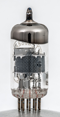
The screen extends above the double top mica and the rectangular cathode of the triode is seen face-on.
The thin glass tube envelope is 20 mm in diameter and, excluding the B10B base pins, is 47 mm tall.
Reference: Data-sheet. Type PCF200 was first introduced in 1964. See also1964 adverts.