The UCC84 and PCC84 double triodes differ only in heater requirements. Both were developed to meet the needs of VHF broadcasting.
The UCC84 was specifically designed for cascode operation. The normal configuration was for triode one to be operated as a grounded cathode stage directly coupled to triode two. Triode two was connected as a grounded grid stage.
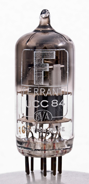
The triode has a smaller inter electrode capacitance than a pentode at VHF and could be made physically small. The photograph shows that within the envelope the electrodes are a small percentage of the total volume. The two triodes would be used for initial signal amplification at up to 250 MHz. The low anode voltage and relatively high current being features to ensure low noise operation. The anode dissipation was two Watts for one triode or 2.5 Watts for both triodes operating.
Most televisions used series heater chains at 300 mA consumption but small sets with fewer valves used the 100 mA series valves.
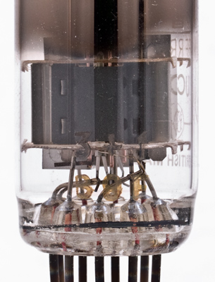
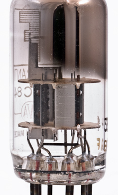
The grids are wound on copper supports for better heat conduction. The cathode is coated onto a rectangular tube. The insulated heater can be seen entering the cathode. The anodes are carbonised to act as better heat radiators.
The bright metalwork is the screen. This image also shows the top and bottom micas and the triode sections are a small part of the height of the envelope.
The thin glass tube envelope is 20 mm in diameter and, excluding the B9A base pins, is 47 mm tall.
References: Data-sheet & 1040. Type UCC84 was first introduced in 1954. See also1954 adverts.