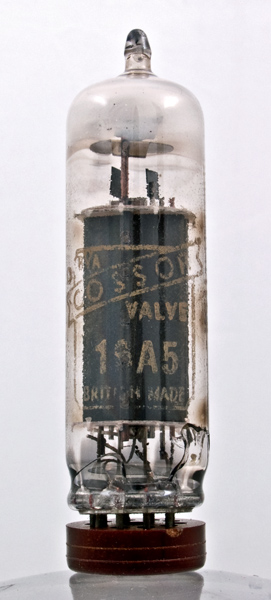
The 16A5 was designed for low frequency power output either as a television frame output valve or for audio use.
This valve would normally be found in audio stages of television receivers. A pair used in push pull class AB1 would deliver 9 Watts at 4 % distortion. The peak to peak grid signal voltage would be 26 Volts and the shared anode load would be 4,000 Ohms.
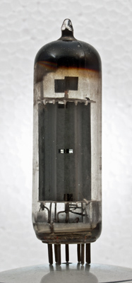
The valve from the side. This was an ebay acquisition and the pins were very badly bent. Although straightened gently the enveloped cracked and the vacuum was lost. These pictures were taken shortly afterwards but the getter turned milky quickly. It later turned white.
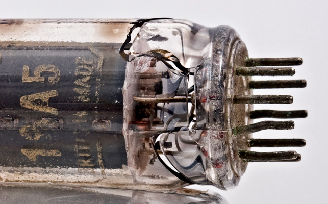
A close-up of the cracks in the glass.
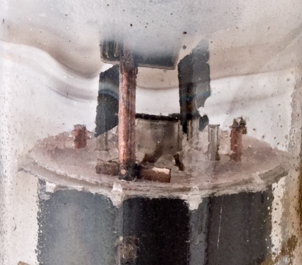
The top of the electrodes and the heat sink fins on the control grid supports are clearly seen. The Cossor logo in yellow ink.
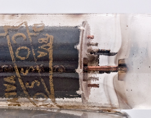
The The getter holder is fixed to the top of one of the Copper anode support rods. Unusually the suppressor grid is wound on Copper supports.
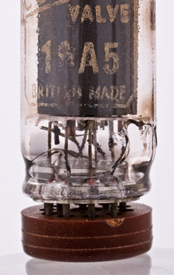
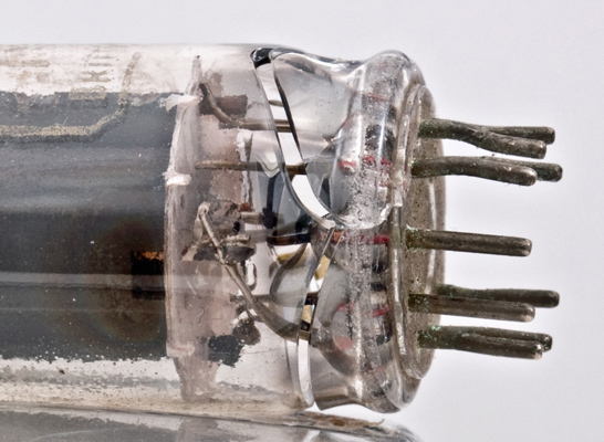
The envelope slightly separated from the base. The pins were almost straight when the envelope failed.
The break is at the reduced diameter section and to withdraw the electrodes would require a smashing of the bulb.
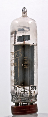
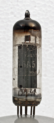
Another 16A5 in the museum, poor lettering but intact.
Through the slot in the side of the anode the three wire grids can be seen.
The thin glass tube envelope is 20 mm in diameter and, excluding the B9A base pins, is 69 mm tall.