|
A superheterodyne employing a limited number of valves is now capable of a performance which comes as something of a revelation to those who are accustomed to the results given by older sets of similar types. Careful design and in this article the chief factors which govern the choice of circuit are discussed.
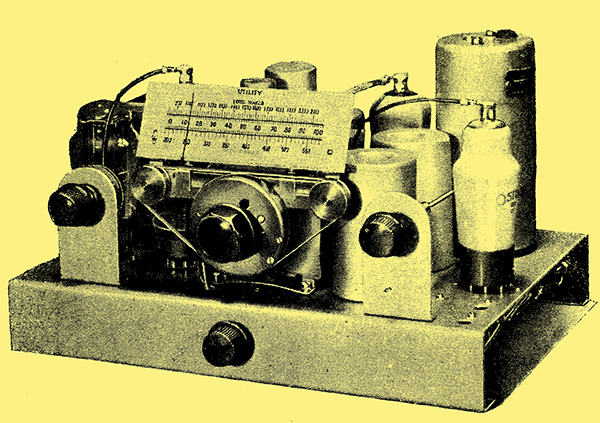
The three-valve superhet in practical form. The construction of this receiver will be described in the next two issues of this journal.
The day is long past when a superheterodyne necessarily included eight or more valves, and thanks largely to modern valve development it is now possible to build a set having a very high standard of performance which employs no more than three receiving valves. It is true that one or more of these may be double valves, but in popular parlance they count only as single specimens.
A superheterodyne for loud speaker operation must include a frequency-changer, an IF amplifier, a detector, and an output valve. This is the bare minimum, and in days gone by would have necessitated five valves at least, since two were needed for the frequency-changer. To-day, three valves only are needed, for one of the combination diode types can well serve as a combined detector and output valve. Thus all the functions essential to the superheterodyne can be performed by three valves, but this alone does not mean that the receiver will be satisfactory. It is far more important that the set should be sensitive, have adequate selectivity, and give good quality reproduction than that it should be of any particular type which happens at the moment to be fashionable. These characteristics are, however, most easily and cheaply obtained with the superheterodyne, but careful design is essential if a good performance is to be secured with such a limited number of valves.
A diode detector is essential it distortionless rectification with a satisfactory AVC system is to be obtained at low cost, and the output stage must be fed directly from the detector, for an IF stage is needed, and there is then no valve to spare tor an intermediate LF stage. Transformer coupling immediately following a diode is ruled out by considerations of quality of reproduction, so that the output valve must be fed from the detector through a resistance-capacity coupling. There is then no alternative to a high-efficiency pentode for the output valve, for such a valve requires only about one-tenth the input of a triode for the same output. As such valves are available fitted with two diodes, the valve for the detector, AVC, and output stages is naturally a duo-diode-output pentode.
For the IF stage, an HF pentode of high mutual conductance is an obvious choice, and for the frequency-changer one of the special valves developed for this purpose. The precise type of valve used must be selected on its performance, and for a set of this nature the triode-hexode has certain advantages over other types. It has, for instance, an unusually high AC resistance for its conversion conductance, and this is of importance in securing high selectivity.
The Intermediate Frequency
Having tentatively selected the valves and decided upon the functions which they must perform, one very important question must be answered before the design can proceed any farther. What intermediate frequency shall be used, 110 kHz or 465 kHz? The low frequency will permit both higher amplification and selectivity to be obtained, but two signal-frequency tuned circuits will be essential if second-channel interference is to be kept at a reasonably low level. With a frequency of 465 kHz, however, it is not difficult to obtain variable selectivity, and the reproduction is likely to be better than with the lower frequency; moreover, a single signal-frequency circuit will suffice for second-channel rejection if correctly designed. The higher intermediate frequency is thus likely to prove somewhat cheaper than the low as well as having certain technical advantages. It is, consequently, the one to choose, provided that experiment shows the amplification and selectivity to be adequate, even although they may not be as high as at the lower frequency. It may be said at once that experiment does show it to be readily possible to obtain adequate amplification and selectivity at 465 kHz.
Two IF transformers are required for the IF couplings, and that coupling the IF valve to the detector must have coils of high dynamic resistance if good IF amplification is to be secured. The coils in this circuit, however, are inevitably damped by the detector and AVC system, so that at this point selectivity can receive less consideration than amplification, and the coils in the IF transformer should be of high inductance and high dynamic resistance, but not necessarily of high Q. To secure the full amplification the coupling between the two coils comprising the transformer must be optimum when the coils are damped by the external circuits. This means that the coupling must be somewhat greater than the optimum for the transformer alone.
In the case of the transformer coupling the frequency-changer to the IF valve, the dynamic resistance of the coils is again of importance as affecting the amplification. Since this circuit is quite lightly damped, however, it is more beneficial to concentrate upon selectivity than upon amplification. It is thus of primary importance that the coils should be of high Q (Q = ωL/R), and this is most readily achieved with a moderate value of inductance leading to a moderate dynamic resistance. In order to obtain variable selectivity the coupling between the coils in this transformer can be adjustable.
The signal frequency tuning system can now receive attention. Owing to the use of an intermediate frequency of 465 kHz, second channel interference on the medium waveband occurs almost entirely from stations on lower wavelengths than those devoted to broadcasting. As such transmissions are usually weaker than broadcasting stations less pre-selection is needed than if a low intermediate frequency were used, and, moreover, the protection against interference afforded by each tuned circuit used is much greater than would be the case with a, low frequency. On the long waveband, however, stations which can cause interference are in the medium wave broadcast band. Owing to their greater strength a higher degree of pre-selection is needed on the long waveband than on the medium, and it is fortunate that this is obtained almost automatically, for the selectivity of long-wave circuits is inherently greater than that of low, the Q of the coils being in each case the same.
Experience shows that when the pre-selector contains only a single tuned circuit the protection against second channel interference is barely adequate for average needs when conventional methods of aerial coupling are used. Moreover, with such a coupling the efficiency of the pre-selector varies considerably over the waveband, while the aerial affects the tuned circuit to such a degree that ganging is difficult unless stray capacities are kept at an unusually low figure. Now, an examination of the problem of second-channel interference shows that on the medium waveband of 550-1,500 kHz it can only occur from stations in the band of 1,480-2,430 kHz, and that, except for the two channels of overlap, this second-channel band is distinct from the receiving band. Similarly, for the long waveband of 150-300 kHz, the second-channel band is 1,080 - 1,230 kHz, which is very different from the receiving band. Since the receiving and second-channel bands are distinct it is possible to employ a fixed filter system to increase the preselection rather on the lines adopted in single-span receivers. In this way it is possible to obtain any desired degree of second-channel rejection while retaining only one variably-tuned signal-frequency circuit.
The Pre-Selector
In practice, however, it is found that a very simple arrangement increases the pre-selection to an entirely adequate figure, and it has the further advantage of relieving the tuned circuit of much of the loading effect of the aerial, and of permitting the use of a method of aerial coupling which leads to unusually constant sensitivity through the tuning range. In addition, an increase in efficiency, as compared with the conventional arrangement, is secured. The arrangement adopted will be fully described in The Variable Selectivity IV, and in the meantime it will suffice to say that it consists of inserting in series with the aerial a loading coil of such value that the aerial circuit as a whole is resonant at the middle of the receiving band and of coupling the aerial circuit to the tuned circuit by a combination of two forms ot capacity coupling.
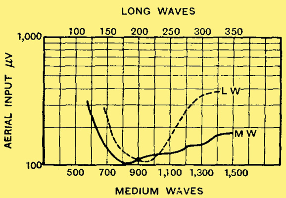
Fig. 1. -These curves show the high sensitivity obtained with a three-valve superheterodyne. They are for an output of 50 milliwatts at 30% modulation.
The use of this aerial coupling system has been found to lead to a big improvement in performance, and a three-valve superheterodyne designed in accordance with the principles which have been briefly discussed in this article can give an astonishingly good performance. The sensitivity is shown by the curves of Fig. 1, in which the dotted line represents the performance on the long waveband. The curves show the aerial input needed to obtain the standard output of 50 milliwatts at 400 Hz with 30% modulation. Over the greater portion of the medium waveband the sensitivity is better than 150 microvolts, and at 950 kHz it is nearly 100 μV. At its worst point it is 330 μV. On the long waveband the point of maximum sensitivity is the same as on the medium waveband, and the variations over the band are very little greater. The long wave performance is, in fact, exceptionally good, for in most receivers the sensitivity is much lower on the long than on the medium waveband and varies to a greater degree.
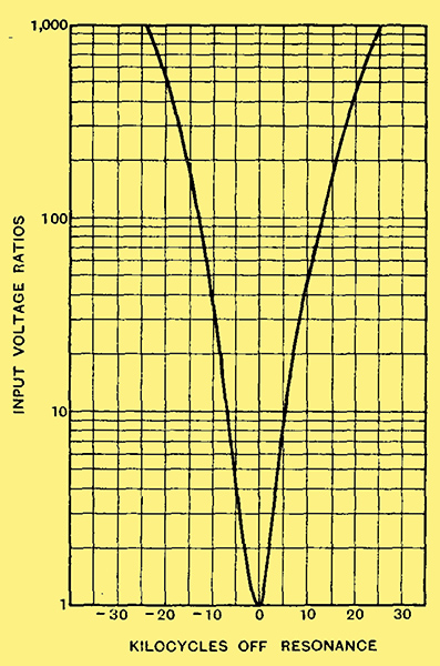
Fig. 2. - This curve shows the selectivity at 1,000 kHz (300 metres) with the selectivity control set for maximum sensitivity.
The selectivity at 1,000 kHz is shown in Fig. 2, and the curve was taken at the optimum setting of the variable selectivity control, that is, the same setting as that used for the sensitivity measurements. It does not, therefore, represent the maximum selectivity, for it can be increased at the expense of sensitivity. The curve shows good selectivity, the response at 10 kHz off resonance being 1/500 that at resonance on one side of resonance and 1/300 on the other.
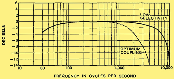
Fig. 3. - The fidelity at two different settings of the selectivity control is shown here and will be seen to be exceptionally good.
It is the fidelity which is so striking tor a receiver of this class, however, and Fig. 3 shows that an exceptionally good performance has been secured. With low selectivity the response falls by only 6 dB at 8,000 Hz and by 3.6 dB at 30 Hz. The curves have been taken with a constant resistance load and consequently do not show the rise in the treble which occurs when the output pentode is associated with a loud speaker, and which still further improves the performance. With optimum coupling in the IF transformer the treble response naturally falls off as indicated by the dotted curve. The variable selectivity control can thus be used as an effective tone-control should this be thought desirable.
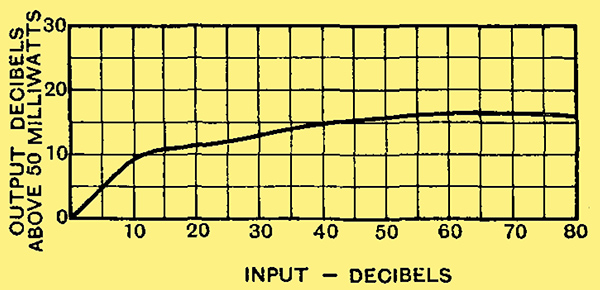
Fig. 4. - The AVC system comes into operation with an input 9 dB above that needed for 50 milliwatts output, and maintains the output at an unusually constant level.
Fig. 4 shows the performance of the AVC system. It commences to operate for an output of 9 dB above 50 milliwatts (for 30% modulation), and a change of input of 74 dB causes a change of output of only about 7 dB. That is, a change of input power of 25 million to one causes a change of output power of only five to one!
It will be clear from the curves that the performance given by a well-designed three-valve superheterodyne can be extraordinarily high, and this is confirmed by practical tests on signals. The fact that the receiver is small and inexpensive and employs few valves does not mean that its performance is in any way small.
|