|
The triode Hexode
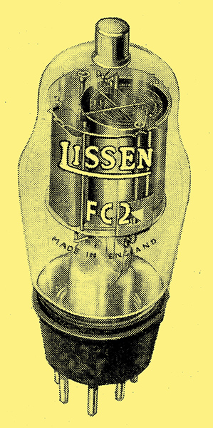
The Lissen FC2.
As a frequency-changer the popularity of the heptode is well deserved, but it is shown in this article not to be entirely free from defects which are of particular importance on short wavelengths. The author describes a new valve - the triode-hexode - which is especially designed to overcome these faults.
The function of the frequency-changer of a superheterodyne is well known, and it will be remembered that until recently two valves were employed. One valve operated as an oscillator, and its output was applied with the incoming-signal to the other valve, which functioned as a detector - the desired intermediate frequency being obtained in the output of the detector and being equal to the difference between the signal and oscillator frequencies. At a somewhat later date the triode was superseded by the screen-grid valve for the first detector, with a considerable improvement in efficiency.
Although such an arrangement is capable of giving a good performance, it suffers from two major disadvantages - interaction occurs between the signal and oscillator frequency circuits, and radiation from the aerial is likely to occur unless a signal-frequency HF stage is used. These disadvantages can be minimised by careful design, but they cannot be completely avoided. They occur to an even greater degree with later frequency-changers in which a single screen-grid or HF pentode valve is used in an endeavour to reduce the cost of a receiver. Such frequency-changers have the additional drawback that they cannot be biased for volume-control purposes.
It was in an endeavour to overcome these defects that the now popular heptode and octode were developed, and they very largely overcome the defects of the earlier types. They suffer from a disadvantage of their own, however, which has for some time been rather obscure.
Interaction in the Heptode
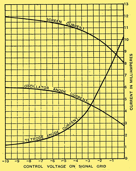
Fig. 1. - The variation of current to the different electrodes of a heptode when the grid bias is altered is shown by these curves.
The operation of the heptode has - been previously dealt with [★] The Pentagrid Converter, by Claude L Lyons, BSc, The Wireless World, May 12, 1933. here and it will be remembered that the seven electrodes all lie in a single electron stream, so forming a true single-valve frequency-changer. Despite statements to the contrary, a change in the voltage applied to either the control grid or the oscillator anode affects the currents flowing in the circuits attached to the positive electrodes. Some of these effects are necessary, of course, for the proper operation of the valve, but others are distinctly undesirable.
As an illustration, we may consider the action of the oscillator electrodes. The oscillator grid controls the electron stream in order to provide the proper 'coupling' to the detector section of the valve. The potential of the oscillator anode, however, is always in opposite phase to that of the oscillator grid, so that it partially neutralises the effect of the latter. This effect is by no means serious, but it occurs to a greater degree in many British heptodes than in the original American pentagrids, for in some of the later valves the oscillator anode bars have been placed more directly in the electron stream in order to obtain a higher oscillator mutual conductance.
Another effect of similar nature, however, is responsible for much more serious consequences. When the negative potential applied to the control grid is increased, the detector anode current falls, while the screen and oscillator-anode currents both rise, as shown in Fig. 1, for a representative heptode. It will be seen that there is consequently a negative mutual conductance between the control grid and the oscillator anode, and because of this a signal applied to the control grid can cause the oscillator anode voltage to vary in sympathy.
The practical result of this appears as interaction between the signal-frequency and oscillator circuits. The effect may not be very evident on the medium and long wavebands, but it may assume great importance in short-wave reception where the ratio of oscillator to signal frequencies is very small. The effect has been dealt with in a paper by Klipsch, to which reference should be made for a full discussion of the phenomenon [★] Suppression of Interlocking in First Detector Circuits, by Paul W Klipsoh, The Proceedings of the Institute of Radio Engineers, June 1934..
The Triode-hexode
The amplified signal-frequency voltage which occurs on the oscillator anode in the manner just described can be transferred back to the control grid by the inter-electrode capacity between the oscillator anode and control grid, for the screening between these electrodes is necessarily imperfect. The effect of this feedback depends upon the phase of the voltages concerned, and this in turn depends upon whether the oscillator circuit is tuned to a higher or lower frequency than the signal-frequency circuits. In the ordinary superheterodyne the oscillator circuit is tuned to la higher frequency than the signal-frequency circuits, and the feed-back is consequently anti-phase and reduces the efficiency. It can be shown experimentally that if the oscillator be tuned to the other beat the feed-back is in phase with the signal, and increases the efficiency to such a degree that in some cases instability may result.
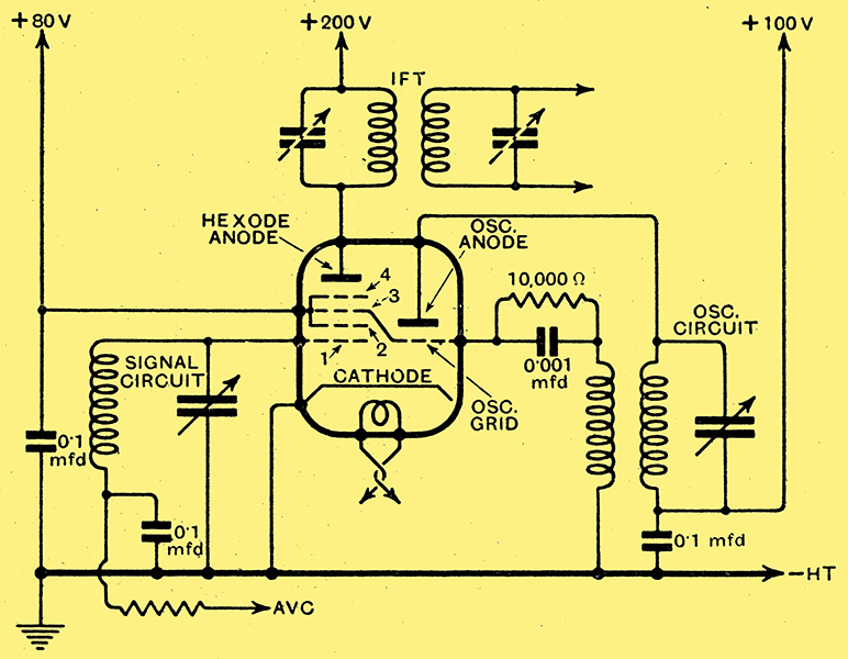
Fig. 2. - The connections of the triode-hexode in a typical frequency-changer circuit show that they are little different from those adopted for a heptode.
In order to overcome these disadvantages of the heptode, a new valve of the electron-coupled type has been designed and is known as the triode-hexode. It consists of two separate valves built into a single envelope one a triode and the other a hexode. The arrangement will be clear from Fig. 2, and it can be seen that the triode acts as the oscillator with any conventional circuit. The hexode has six electrodes, a cathode, control grid, two screen grids, a coupling grid, and an anode. The control grid (1) immediately surrounds the cathode and is itself surrounded by the first screen grid (2). The coupling grid (3) comes next, and is separated from the anode by the second screen grid (4); in practice, the two screen grids are connected together internally and are brought out to a single pin in the base. The coupling grid (3) is also connected internally to the triode grid, so that the valve has only a seven-pin base, the connections to which are arranged in the same way as in the heptode, and a top connection for the control grid.
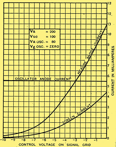
Fig. 3. - The current variations with grid bias for the triode-hexode show that the oscillator anode current is constant.
Variations in the oscillator anode potential have no effect upon the screen and anode currents of the hexode, and changes in the hexode screen, anode, or control grid voltages do not alter the oscillator anode current. An increase in the control grid bias causes both screen and anode currents to fall, as shown by the curves of Fig. 3, thus leading to economy of current in a battery receiver and an increased grid base in a mains set.
In operation, the hexode anode voltage should be as high as possible consistent with the maker's rating, and the minimum control grid bias should be zero for the battery valve and -1.5 Volts for the mains type. The oscillator grid is best self-biased by a grid leak and capacitor, as shown in Fig. 2, and under these conditions there are definite optimum voltages for the screen grids and the oscillator anode. When correctly operated the hexode anode AC resistance is high, and the total current consumption quite moderate, being only 8 mA. for the Lissen AC FC and 4 mA. for the battery model, the FC2. The conversion conductances are 0.65 mA/V. and 0.4 mA/V. respectively, and it will be seen that the ratio of conversion conductance to total current at minimum bias is greater in the triode-hexode than in the heptode, and at least as good as that with the conventional two-valve frequency-changer or its equivalent, the triode-pentode. This ratio is of importance in comparing different frequency-changers, because it governs the amount of background hiss found in the reception of a weak signal. Background hiss is due to ionisation of the minute trace of gas remaining in the receiving valves, and for a given valve is proportional to the total current passing. The noise from the valve in the first stage of a receiver is the most important, because it is amplified by the succeeding stages. For both these reasons, maximum background hiss occurs at minimum bias when using variable-μ HF valves.
If one assumes that the valve manufacturers offer valves of equal 'hardness', the valve selected for the first stage should be the one having the highest ratio of mutual conductance to total current at minimum bias, or for a frequency-changer valve the highest ratio of conversion conductance to total current at minimum bias, for this will be the valve giving the highest ratio of signal to noise. It will thus be seen that the triode-hexode offers important advantages over other frequency-changers in that, While it is non-radiating and can be controlled from the AVC system, it gives complete freedom from interaction between the signal and oscillator frequency circuits and also a lower level of background hiss. These points are, important in normal broadcast reception, but they are doubly so on the short wavelengths.
|