|
Where substitutions are desirable, merely permissible, or slightly risky.
Although the replacement of an old valve by a new one of improved characteristics will generally be beneficial, instability may sometimes result from the change. This article shows how such troubles may be avoided, and how to ensure that the new valve may be made to operate under best conditions.
Replacement of valves may be rendered inescapable by sheer decrepitude of the old ones, or may proceed from a desire to obtain some of the benefits of the recent extensive progress in valve design. In any case, it will probably be found that the original types are obsolete and not readily obtainable. So, in all likelihood, the said benefits will be thrust upon one, Willy-nilly.
Some considerable time ago it was pointed out that the putting of new wine into old wineskins is liable to be an uneconomical proceeding, in that the wine will be spilled and the skins marred. The same tendency is present when new valves are plugged into old sets. Both valves and set may suffer, or at least give less than their best; because they were not designed to work in harness. A modern high-slope detector valve, for instance, substituted for an told type, might take an altogether excessive current; and, besides being in an unsuitable adjustment for best performance, would give both itself and the battery (if any) a short life.
New valves, then, must be used with circumspection. Many of them such as heptodes and double-diode combinations are ruled out altogether, because they are not applicable to old receivers. Here we are to consider valves that can be plugged straight in, with (at the most) only minor alterations, such as valve holders or operating voltages.
In what ways, then, do the new valves differ from old ones of the same general types? Catkins, for example, look sensationally different from the glass valves that were previously universal. Actually, they are precisely equivalent to the glass valves bearing the same designations, so far as electrical characteristics are concerned. Their appeal is on the grounds of robustness, consistency, and non-microphony; and these should be given due consideration when the replacement of old-type valves becomes necessary.
Whether the external construction is of metal or glass is of less importance than the electrical characteristics. The trend of progress in this respect has been mainly in the direction of increased slope, alias mutual conductance, or G for short. That means either that the internal resistance (impedance), Ra, has been reduced, or that the magnification factor, μ, has been increased; or perhaps a bit of both. In any case the general tendency is to give more amplification. Just how much more depends on whether the other components happen to be such as to take advantage of the improved valve efficiency.
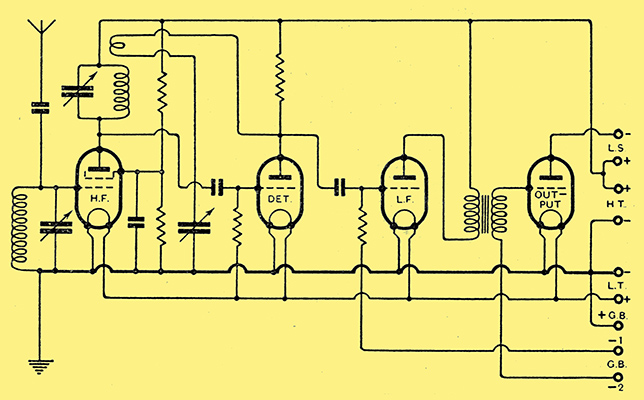
Fig. 1. - Typical circuit arrangement of a receiver designed a few years ago. The effect of substituting new valves is discussed.
But let us get down to something rather more definite. Fig. 1 shows the skeleton circuit of a receiver which, disregarding details such as decoupling, is typical of the practice of a year or two ago. A screen-grid HF stage is followed by detector, LF stage, and output. Your receiver may not happen to have all these stages, but it certainly has some of them.
Take the HF valve first. A typical battery SG valve of the period had a μ of 200 and a Ra of 200,000; G is μ × 1,000 / Ra or 1 milliamp. per Volt in this case. A likely figure for the dynamic resistance of the tuned circuit is 50,000Ω. This means that the valve's amplification of 200 is divided between itself and the tuned circuit in the ratio of 200,000 to 50,000. The tuned circuit, therefore, gets only 50/(200 + 50), or one-fifth of the whole. The amplification that is actually available for passing on to the detector is thus 40.
How Amplification is Increased
This little calculation, of course, is just an example of the way all valve amplifiers work. The coupling is there to extract, as it were, as much as possible of the amplification, μ which would otherwise simply be wasted in the resistance of the valve itself.
Now, suppose the new valve has a slope of 2 milliamps per Volt. If Ra is as before, but μ doubled, then the stage gain is doubled. If, however, μ is as before and Ra halved still giving the same slope - the original μ is divided in the ratio of 100 to 50, and the amplification actually yielded is 200 × 50 / 150 or about 67 - a less pronounced increase.
The response to a transmission which is off tune is increased practically 100% in either case, which means that the response to the wanted station, relative to interference, is unchanged if μ is doubled, but actually deteriorates if Ra is halved. From the point of view both of selectivity and gain it is better to go for a high μ, other things being equal.
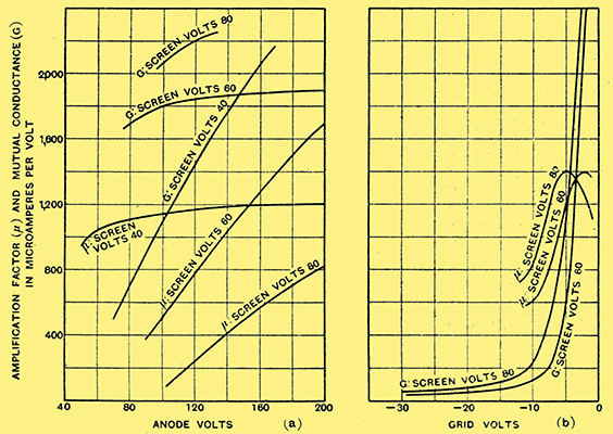
Fig. 2. - Characteristics to order; amplification factor and - slope are determined by operating conditions.
As a matter of fact, the figures given in the valve catalogues can be varied considerably by altering the operating voltages. Reducing the screen voltage increases μ when the negative grid bias is small, and therefore tends to improve selectivity (Fig. 2). Unfortunately, it increases Ra still more rapidly, so there is a net loss in amplification. Still, it is a good thing to realise that the catalogue characteristics are not governed by the immutable laws of the Medes and Persians.
You may perhaps find that the increased amplification with the new valve is too much for stability, and the receiver goes off into self-oscillation. The correct thing is to trace the stray coupling that is the cause of the trouble_try turning the tuning coils round or moving them farther away from one another; but if that is too much bother you can at least make use of the more efficient valve to improve the selectivity by reducing screen voltage until stability is achieved all over the tuning scale.
Rules of Thumb for Bias
The details of correct biasing are fully supplied with the valve; so there is no need to go into it here, except to remark that failure to alter the bias tapping or cathode resistor may cause an excessive current to be drawn. Increased μ generally necessitates reduced grid bias; and decreased Ra increased bias. Sometimes, too, a new valve is found to give much poorer results, particularly if little or no bias is used. This is because grid current starts at a more negative grid voltage and damps the tuned circuit. Obviously, the cure is to increase the negative bias slightly.
It is possible to plug-in a variable-μ valve where a fixed-bias type previously dwelt, for the characteristics with a small fixed bias are much the same. But this is not particularly recommended, because it gives a lower slope for a given consumption of anode current. You may, however, like to consider the conversion of your receiver to variable-μ volume control, which can be done by modifying the voltage-dropping resistors according to the makers' instructions. As a compromise, particularly in battery-driven sets, there is a type between the old fixed-bias valve and the 'long-base' variable-mu; the Mullard PM12M is an example. Instead of needing 20-40 Volts maximum grid bias, 5-10 is enough for volume control. Of course, the control is not so perfect, but it is quite good if something is done to prevent the excessive signal of a local station from being applied.
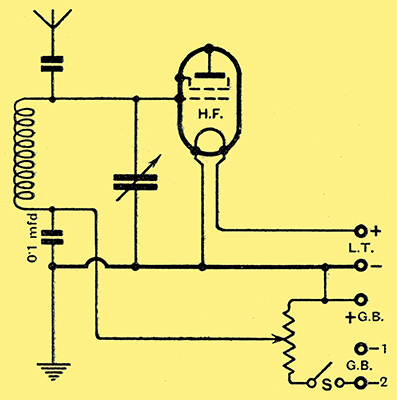
Fig. 3. - Providing adjustable bias for a variable-μ valve.
Fig. 3 shows one way of staging a a variable-μ control. A a volume-control potentiometer is connected across the full grid-bias as supplied to the last valve. This takes current where formerly none was drawn, so a switch S is included to prevent the bias battery from wasting away with probably serious results on the power valve and HT battery. The resistance of the volume control is not important within close limits; about 1,000 Ω for each Volt of grid-bias is a satisfactory figure. Neither is the capacity marked 0.1 μF important - anything from 0.01 to 1.0 may be used.
Incidentally, although μ is pronounced 'mu', a variable-μ valve is really a variable - mutual conductance valve, though it is true the μ is somewhat affected at the same time.
To be really up to date you might short-circuit the more recent SG developments by going straight on to an HF pentode. But remember that, while some have the usual five pins, others are fitted with seven.
How Amplification, Stability and Quality are Affected.
An HFpentode with a 5 pin base may be plugged into any set designed for the corresponding SG valve (variable-μ or otherwise). The other type, which is not readily interchangeable, has a 7 pin base, in order that the suppressor grid and metal coating may be brought out to separate pins. This is necessary in many modern circuits, but we are not discussing them just at the moment. The Mullard VP4 and Cossor MVS-Pen can be obtained 'ready for use' with 5 pin bases.
Generally speaking, the pentodes have slopes about equal to those of the most recent SG types. But the μ is enormous. Unless the dynamic resistance of the tuned circuit is exceptionally high (as with a high-efficiency iron-core coil) the increase in amplification is inappreciable. The other advantage of the HF pentode - ability to handle a very large signal amplitude - hardly concerns us, because only very recent designs require enormous signal voltages to be handled in the HF stages. If the old valve was a high-slope SG type, there is no reason to expect noticeable improvement on substituting a pentode with the same slope. The Mazda AC/S2Pen, however, is rather exceptional with its slope of 6 milliamps per Volt; and if one cares to go to the trouble of fitting a 7 pin valve-holder it is capable of giving a useful increase of gain. Fig. 4 shows how little alteration in wiring is involved in changing over to a 7-pin pentode.
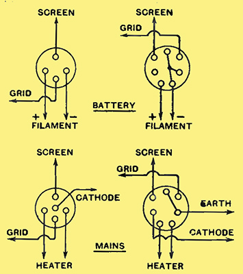
Fig. 4. - Changing over to HF pentodes: appropriate alterations to wiring when 7-pin valve-holders are employed.
To pass on to the detector in Fig. 1; assuming the usual grid-leak type, there is no bias (until a station is tuned in). When a new valve with approximately the same μ but a higher G is chosen, there is a likelihood that it will take an excessive current if it is allowed to. A resistance coupling (which, of course, includes the parallel-fed transformer) does not allow it, because the voltage actually on the valve anode drops correspondingly. But a directly fed transformer may be badly saturated. To avoid this difficulty the high slope may be taken in the form of increased μ. The result is then a proportional rise in amplification, which may not be an unmixed blessing. It increases the tendency to hum, motor-boating, microphony, overloaded output or under-loaded detector. Apart from that, the high-slope triode, with a μ in the neighbourhood of 100, is likely to do more harm than good even to the amplification, by throwing a greater damping on the preceding tuned circuit. Altogether it is a bad move.
Drastic LF Changes
It may, however, be practicable to make use of the efficiency of modern valves to cut out a LF stage entirely. This disposes of a possibly embarrassing excess of amplification; but, of course, the survivors must work double shift. A good way of getting the necessary extra magnification to enable a whole valve to be saved is to use as the detector a SG valve; or, better still, an HF pentode, such as the Mullard SP4. The latter type of valve is less tricky to get right; SG valves are apt to be disappointing unless all the working conditions are just so. But the great merit common to both (in addition to the large amplification) is the absence of damping on the input tuned circuit. Improved selectivity and sensitivity are secured at one stroke.
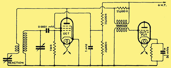
Fig. 5. - An HF pentode, used in this way as a detector, has several important advantages.
Fig. 5 gives the circuit in the case of the Osram MSP4. Whether pentode is used or triode, the increased slope is likely to make oscillation much easier - perhaps too easy. Also, it may be a sound plan to remove a few turns from the reaction coil. A good principle is to use as few reaction turns as will serve the purpose.== In view of the foregoing suggestions, the LF stage shown in Fig. 1 may have ceased to exist by the time we arrive there. It is quite superfluous with modern valves. But, supposing it to be too much trouble to uproot the stage, the same general principles are observed as heretofore, except that the existence of grid bias makes it possible to exercise more control on the anode current. Study of this point is particularly worth while in battery sets. It is seldom necessary or desirable to take more than about 2 milliamps.
Estimating Overall Magnification
The results given by resistance-coupled stages are calculated in just the same way as for HF stages, with this advantage, that the actual anode coupling resistance is much more likely to be known. On the other hand, the valve resistance is not quite such a simple matter, because the voltage on it is more or less considerably reduced. The valve resistance is consequently greater - sometimes quite a lot greater - than that specified in the valve list. In most cases one isn't far wrong in taking a figure 50% higher.
Now we come to the last stage. Some very high slopes have been attained by recent valves. There is the Micromesh P.A.1 triode, with 12 mA per Volt, and the Mazda AC2/Pen with 9 mA per Volt. Such valves as these plugged into receivers several years old are not likely to be satisfactory. The AC2/Pen has a 7 pin base, and thus cannot be immediately substituted.
The receiver must be designed to make proper use of these exceptional valves. But a mild degree of stimulation can be quite safely imparted to a rather tired set by careful choice of replacements. As a general rule, assuming that the original valve suited the loud speaker, the best all-round results are given by a new valve in which the higher slope is about equally due to lower Ra (impedance) and greater μ. If anything, the tendency should be in favour of increasing Ra rather than decreasing Ra. It is difficult to make a universally applicable recommendation, for there are so many things to take into account; but provided that one does not abandon oneself recklessly to an orgy of 'slope', things cannot go very far wrong. Adopting the above rule, it is often possible to use the same grid bias as before - a definite advantage when auto-bias is employed. But the question of bias must be carefully gone into with the aid of the makers' slip.
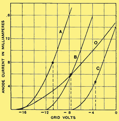
Fig. 6. - How the question of grid bias may be affected when fitting a. new output valve.
Fig. 6 compares curves for typical old and new small power valves, and the effect on the biasing question can be grasped from it. O is the curve for an old valve with a slope of about 1 mA per Volt. It is biased to the point marked - about 7½ Volts. The other three valves are all recent types with slopes of 3 mA per Volt; but A has the same μ and lower Ra, and obviously requires more bias. By the same token it requires more amplification preceding it to drive it fully. The maximum power output is also greater; but, as the impedance is only one-third that of valve O, the loud speaker is no longer properly matched, and the full benefit would not be obtainable without altering the loud speaker impedance to suit it
Curve C relates to a valve having the same Ra, but three times the μ. Considerably less bias is required, and less grid swing to produce full output. The output is somewhat less, but not in the proportion of the bias, so the sensitivity (milliwatts output for a given grid swing) is higher. And the original loud speaker is correctly matched.
Curve B indicates more μ and less Ra: the same bias voltage is quite correct. The same amount of amplification is required of the preceding stages in the receiver, and the output is rather greater. The valve impedance is on the low side for the original loud speaker, but that is a very good fault. The output pentode, being a relatively modern type of valve, has not changed much. New types have been brought out, but the original types have not shown much tendency to increase their slopes. Unless, therefore, the intention is definitely to alter the design of the receiver, there is not much to be said under this heading.
Pentode Valve Bases
There is one point that should not be forgotten when ordering a replacement. Originally, all output pentodes had the auxiliary grids connected to side terminals, the other electrodes being brought to 4- or 5 pin caps for battery and mains valves respectively. Now the side terminal is abolished and 5- and 7 pin caps Substituted. So, unless you are prepared to fit new valve-holders, you must take care to order side-terminal valves.
A quite appreciable all-round increase in working voltages of an AC set, and consequently in undistorted output, can be gained by the simple expedient of substituting a rectifier of low internal resistance, such as the Micromesh R series, for an old type. As these, and a number of other makes, have slow-heating cathodes, there is no danger of the greater voltage jeopardising the smoothing capacitors, because it is not applied until the load of the other valves has come on.
If, before embarking on valve replacements, the decoupling arrangements were no more than just good enough, the probability is that they will not be good enough when more lively valves are in operation. It is not always very easy to tell when this is so. Long before actual motor-boating or other obvious signs of distress set in, there is distortion or loss of amplification, or both. So, in cases of doubt the decoupling should be augmented, or introduced if none exists. Decoupling can be made more effective by increasing either the resistance or capacity comprising it; but, in order to avoid dropping too many HT Volts, the latter alternative is usually to be preferred.
DC working is in a class by itself, and a most unhappy one. Valve designers seem to have been unable to make up their minds what to do about DC, because every new batch has a different heater current. This wouldn't much matter with anything else, but on DC it matters vitally. All the current goes through all the heaters in series, so substituting a valve rated at a different heater current or voltage throws the whole set into confusion. It is a nasty business.
In any case, indirectly heated DC valves are quite recent, and so hardly come within the scope of this article. And the earlier DC sets were most unpleasant pieces of work, using all sorts of makeshifts, such as ordinary battery valves run in series. It is a case for set replacement rather than valve replacement.
|