|
Why distortion is expressed in terms of harmonics, and why amplifiers sometimes give rise mainly to second harmonics, but in other cases produce third harmonics, is fully explained.
The production of harmonics by an amplifying valve whose characteristic is not strictly linear is such a familiar idea that we rarely stop to ask how these harmonics are produced or how their magnitude may be estimated. The phenomenon may be most easily understood by comparing the wave-forms resulting from certain combinations of harmonics with the distorted wave-forms produced from a simple sine wave by various curved characteristics.
Triodes
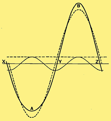
Fig 1. - Second harmonic causes unsymmetrical distortion of the fundamental and may be represented by the addition of a DC component which represents some degree of rectification.
Suppose, for example, that we have a fundamental and 5% of second harmonic with the relative phases shown in Fig. 1. If we take the peak amplitude of the fundamental as I00, the resultant of the fundamental and 5% of second harmonic will be 95 at A, where they are exactly out of phase, but at the positive peak B, where they are in phase, the amplitude will be 105. Thus 5% of second harmonic corresponds to a wave which has been distorted so that the amplitudes of its two halves are in the ratio of 105 to 95, or approximately 10 to 9. This gives the rule that for 5% second harmonics the two valves of the load-line (plotted on the anode current - anode Volts diagram) are in the ratio of 10 to 9, for the distances from the operating point of the two ends of the load-line represent the amplitudes of the two peaks on maximum input.
In separating the alternating currents from the direct currents in any circuit, an alternating current can be defined as one whose mean value over a whole cycle is zero, since it is alternately positive and negative. All the alternating currents of Fig. 1, therefore, have the same zero line as the fundamental. But the output must be zero whenever the input is zero, and this occurs when the fundamental, which constitutes the whole of the input, crosses the zero line. Since the second harmonic is at its maximum at these points, the only way to satisfy the condition without disturbing the AC components is to add a DC component, represented by the dotted line in Fig. 1, which will reduce the resultant to zero at the points X, Y, Z. we therefore say that the output consists of fundamental, second harmonic and a DC component. This latter can be observed on a milliammeter as an increase in anode current, and is thus used as a test for distortion.
Since a certain amount of direct current has incidentally been produced from an alternating input, this distortion is sometimes called rectification, and it is interesting as a demonstration that any unsymmetrical characteristic must rectify to some extent. Another consideration is the effect of distortion on the power efficiency of the valve. Since power is proportional to the square of either voltage or current, and the input must be sufficient to swing up to the larger peak, we take the input power as proportional to 1052, while the output power is 1002 of fundamental and 52 of second harmonic. In the absence of distortion the output would be 1052, so that the loss of total power is 1052 - (1002 + 52), which represents 8.86%. In this case the lost power might be thought to be accounted for by the DC component, which is of no use in the loud speaker or other load, but it is better regarded from the point of view explained in connection with third harmonics.
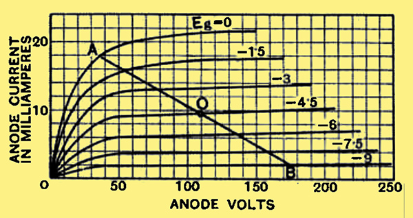
Fig. 2. - In a pentode overloading may occur at both ends of the load line, which restricts both peaks of the fundamental and gives rise to third harmonic distortion.
With a single triode the load-line is distorted unsymmetrically because of the lower bend in the anode characteristic. But with a pentode both ends of the load-line AOB (Fig. 2) may be cut short, one by the ordinary anode bend and the other by the closing up of the curves at the region A.
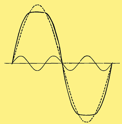
Fig. 3. - The presence of third harmonic reduces both peaks of the fundamental symmetrically. For the sake of clarity the amplitude of the harmonic in this figure and in Fig. 1 has been exaggerated.
An examination of Fig. 3 shows that a third harmonic represents this effect of reducing both peaks symmetrically, since the harmonic is then always out of phase with the fundamental at the peaks. Hence the distortion produced by a pentode may be mainly third harmonic. Actually the pentode load-line is not exactly symmetrical, so that there may be a certain amount of second harmonic in addition. So far we have only considered the peaks of the wave-form, but it is obvious from the figures that the harmonics will represent changes in the other portions of the wave as well. Consequently, where a simple second or third harmonic represents too much distortion in some parts of the wave, other harmonics of higher order must be introduced to counteract the effect of the lowest harmonics where they are not required; but they will be largely even harmonics in the case of unsymmetrical distortion (triode) and odd harmonics with symmetrical characteristics (pentode, push-pull, etc.). It is usual to assume that in practical amplifiers these higher harmonics are of such small magnitude that they do not appreciably affect the amplitudes of the peaks of the waveforms.
Class B and QPP
With Class B there is some risk of distortion of the middle of the characteristic as well as the ends. For if the valves are under-biased they will both be in action at once for small voltages, and so will over-amplify the middle portion of the ware near the zero line. If, on the other hand, the valves are over-biased, they will neither of them function properly on small inputs, and this portion of the wave will be insufficiently amplified. Now in Fig. 3 the third harmonic adds to the fundamental at points near the zero line, so that there is here an increase in the amplification of the part of the wave near the zero line. But we cannot reverse the phase of the third harmonic to represent a decreased amplification near the zero line, for this would also reverse the effect at the peaks; so, for this case, we must replace some of the third harmonic by fifth harmonic to produce the desired effect. It would be interesting to investigate whether there is any difference in the degree of distortion which will pass unnoticed in the two cases; probably fifth harmonic would be preferable, and in the interests of economy the valves are far more likely to be set for this condition.
With QPP there will normally be no grid current, so that only the centre of the characteristic, and not the ends, will be distorted. Accordingly we may adjust the phase of the third harmonic to suit the distortion of the middle of the wave, but we must always bring in appreciable amounts of higher harmonics to restore the peaks to their undistorted form. Inaccurate matching, however, will introduce second harmonic by destroying the symmetry.
Since power is proportional to voltage squared, the peak of the wave-form has a predominant effect on the power output, and an increase in amplitude at points near the zero line cannot balance an equal decrease at the peaks; consequently, a distortion of the wave-form means that for a given amplitude the power is not the same as it would be with a pure sine wave. With second harmonic we have already found that the output was decreased by the distortion, and with Class B it can be shown that 5% third harmonic caused by curtailing the ends of the load-line results in a power loss of 9.5%. The calculations for QPP are more complicated, but since the peaks are unaffected by the distortion we may expect the change in power to be small. It is clear.from Fig. 3 that the third harmonic is zero whenever the fundamental is zero, so that we require no DC component when the distortion is symmetrical, and third harmonic is accompanied by no change in mean current. Consequently, the anode current meter gives no indication of this distortion, and we must rely upon the ear or use an analyser which can measure the amplitudes of the separate AC components.
|