|
A project to build a pair of valve amplifiers without AC mains input.
The author built a pair of mono-bloc EL95 push-pull amplifiers in 2016 powered by an old laptop brick with a 15 Volt output. These open board amplifiers function well but the design was limited to 10 Watts HT by the available audio grade HT generator. An output of 2.5 Watts was obtained with a reasonable frequency response but nothing like the excellent performance of the 6V6 amplifier built from a Chinese kit, and the open board construction was experimental not domestic.
40 Watt HT generators are available from ebay suppliers. These are not designed for audio amplifiers but the output can be cleaned-up and has powered several experimental amplifiers. For home construction and testing keeping the AC mains out of the project should safely encourage a new generation into valve audio.
As the amplifiers were planned for a domestic environment it was vital that they were housed properly. Die-cast boxes provide a ready-made basis for construction and look presentable. With audio files stored digitally and output from a laptop no pre-amp or controls were deemed necessary. Thus a small box would suffice. The Hammond 1590 series was selected. The dimensions were 187 x 119 x 56 mm. 187 was considered the minimum length to allow for air movement around the output valves.
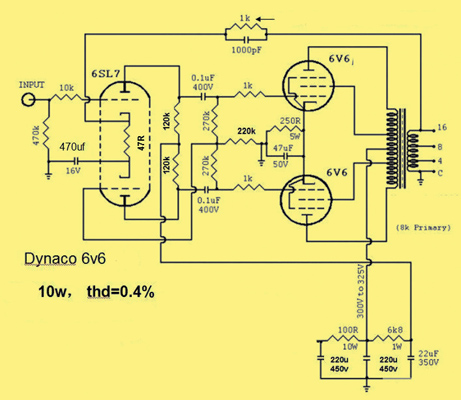
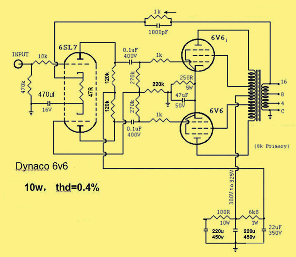
The circuit of the Dynaco amplifier.
The 6V6 beam tetrode has a proven track record of excellence going back many decades and a push-pull pair give 10 Watts without abusing the ratings. Searching for ideas brought up the basic kits available from Chinese suppliers. The presence of a ready-made professional circuit board makes construction quite simple.
These kits are based on the Dynaco circuit as given above. There is no obvious cathode bias resistor for the double triode - but it is there. The negative feedback resistor in series with the transformer secondary acts as the cathode bias resistor. When initially testing the amplifier the feedback input has to be returned to ground.
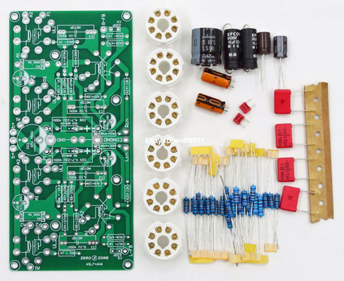
An example of the Chinese kit from ebay.
Other projects had successfully used transformers from VVT Transformers [★] no longer trading but for this project a pair of Hammond 1608A transformers were selected. The selection was made on both technical and aesthetic grounds - black painted and fully shrouded suitable for top of chassis.
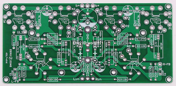
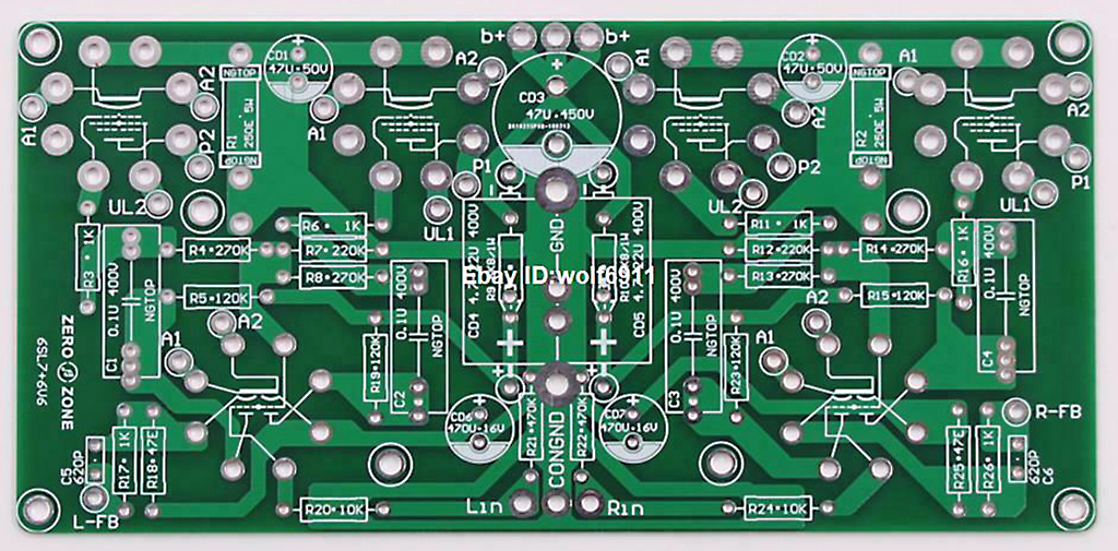
The circuit board as supplied.
The board with the kit was designed to form a stereo pair and final smoothing is on board. The design offered the opportunity to for dividing into two and to supply HT from the DC-DC system.
The board was carefully divided along the centre-line and cleaned-up. The exposed copper track ends would have to be kept away from the inside of the chassis. Two of the original fixing holes would be used to hold the board but two other fixing points were required on the other side. The connection point for the signal input was enlarged for one fixing and the main HT input connection point formed the final corner fixing point. Nylon stand-off pillars solved both the vertical spacing need and provided adequate isolation from the chassis - essential.
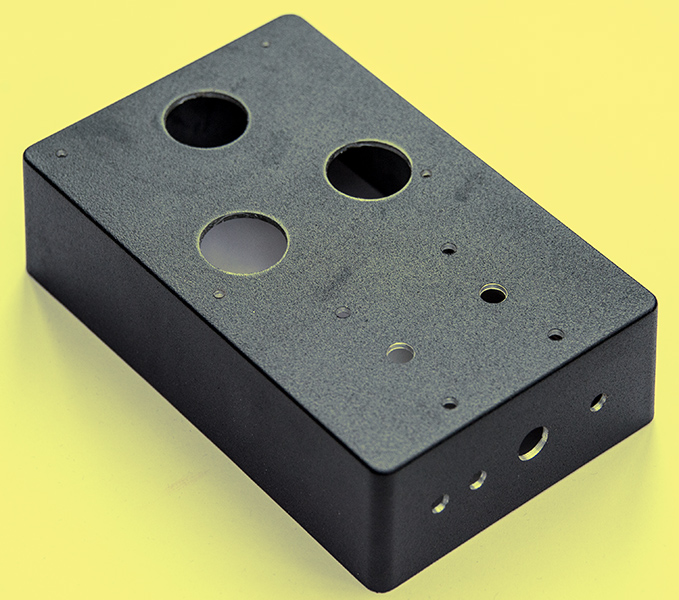
The second (right channel) die-cast box ready for assembly.
To have the input valve on the centre line of the chassis was considered the correct way to go. This required some shaping of the board to fit the box. Also the centre pillar of the die-cast box had to be filed down at the base to accommodate the stand-off pillars. To cut the holes for the valve holders a 27 mm diameter Q-Max style cutter was purchased. Next came the need to place the holes in the precise position. To this end a paper template was prepared. On the board the centre points of the valve holders were marked with a white dot. These dots were drilled through with a 1 mm drill so that the template could be accurately made. After double checking, the template was fixed to the box with masking tape and 1 mm pilot holes drilled through the paper. The holes were then expanded to the correct sizes. The transformer fixing were made in the same way. The DC input, Audio-in and Speaker out holes were drilled in the back wall of the box.
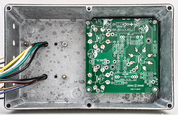
The first die-cast box with left channel circuit board and output transformer in place.
To fix the valve holders in place they were inserted into the board but not soldered. The board was then fixed in place with the correct width of spacer. This required the nylon pillar and a small 3 mm washer to give the total distance of 12.5 mm. With the board in place and the valve holders sitting in the centres of the chassis holes the pins were folded over and soldered into place.
With the valve holders in their correct position the board was removed to allow the rest of the components to be added. The board had all the values printed on the top side and this made the task easy to follow. Following normal practice the resistors were added to the board followed by the capacitors.
The cathode resistor required is 250 Ω at 2 Watts dissipation. The kit was supplied with three 750 Ω resistors of one watt each. Not a bad idea and the circuit will fail safer with multiple components.
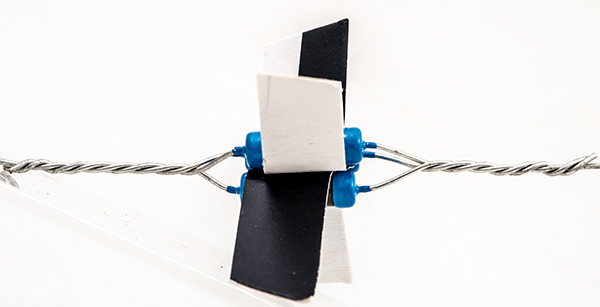
The three cathode resistors.
There should be space around each resistor and so strips of card were inserted around each one after the first end wires were twisted together. With the card in place the other end wires were twisted.
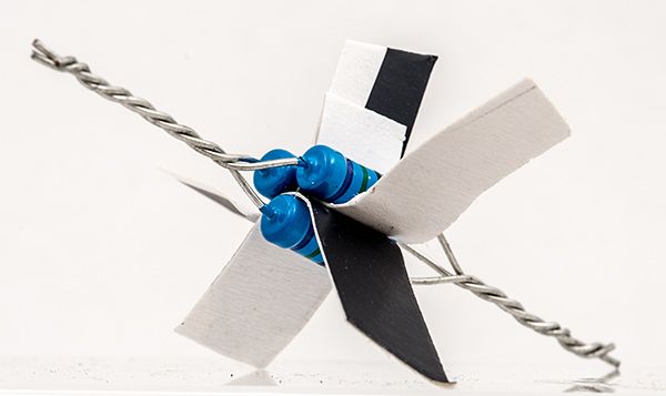
A resistor triangle.
After building the circuit board it was initially tested with the second Hammond transformer. This revealed the correct way to connect the transformer to the board and discovered the problem of not grounding the feedback input. A day of fault finding could find nothing amiss but still nothing worked. Finally the following morning the obvious was seen. Grounding the feedback input enabled the correct circuit conditions to be observed. Connecting the transformer into the circuit indicated that the transformer was connected to the output valves such that the 16 Ω output needed to be grounded to prevent positive feedback. Time to reverse the leads to the push-pull pair.
The board has the output valves marked as 1 and 2. The blue and blue/yellow wires should go to valve 1 anode and screen respectively. Valve two has the brown and brown/yellow wires. With this completed the amplifier correctly had the feedback taken from the 16 Ω output tap. The common output wire (black) was grounded to complete the circuit.
The 4 Ω output tap was cut and the end sealed with heat-shrink sleeving. The 8 Ω tap was connected to the speaker terminals. The author has standardised on eight Ohm speakers.
For initial testing of the mono-bloc the heater and HT leads were taken through the chassis via the hole for the DC input socket. The heaters were supplied with DC current limited to 1.5 Amps to limit the in-rush current. HT was supplied from the Heathkit stabilised power supply. The HT was set at 255 Volts. Time to listen to the amplifier.
The amplifier was on-load for 20 minutes initially. When the power was removed the three cathode resistors were just warm to the touch.
The heater supply was changed from the bench power supply to a small DC-DC step-down module with the current limit set to 1.5 Amps and 6.3 Volts. The current limit limits the inrush current and prolongs the heater life. The author prefers to run these Chinese modules at 50% of maximum output or less.
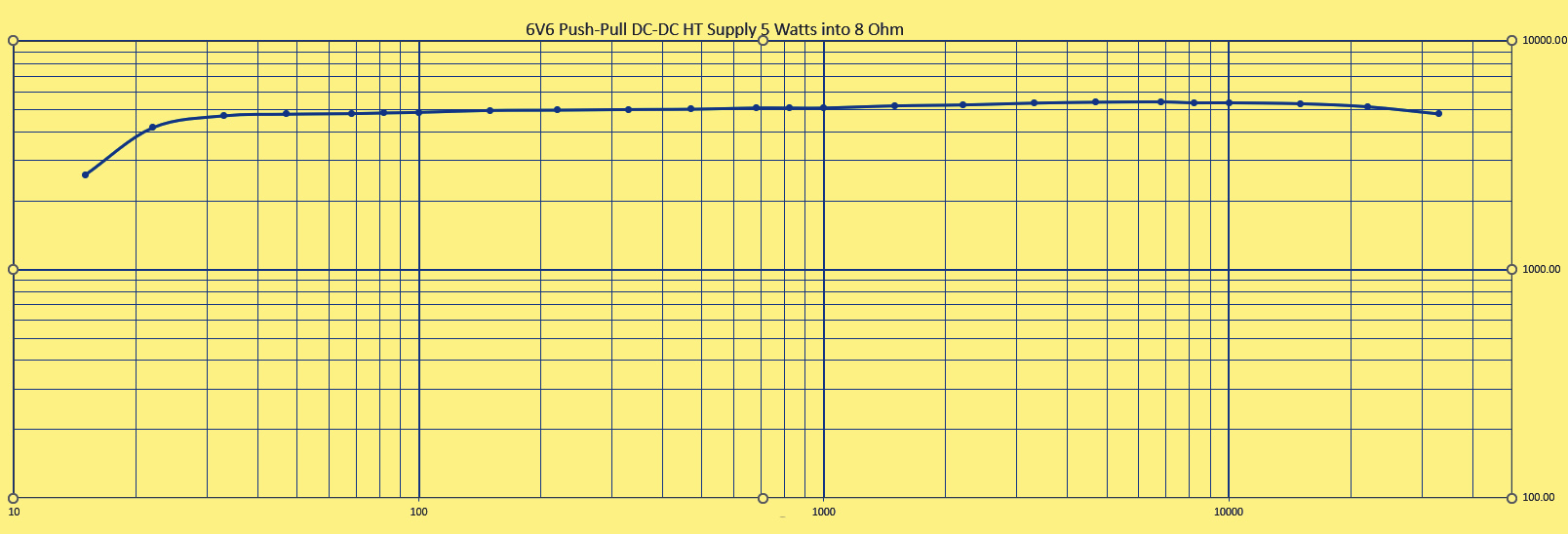
The Dynaco circuit shows an HT rail at 300-325 Volts and the author chose to set the HT at 255 Volts based on the 6V6 data-sheet not wanting, or needing, to extract maximum power from the amplifier. The consequence of the reduced HT is, of course, a reduced maximum power output. On test the amplifier comfortably gives 5 Watts into an 8 Ω dummy load when sine wave testing. As the output pair have cathode bias the measured sine wave performance for 4.2% THD understates the music clean power by 10%.
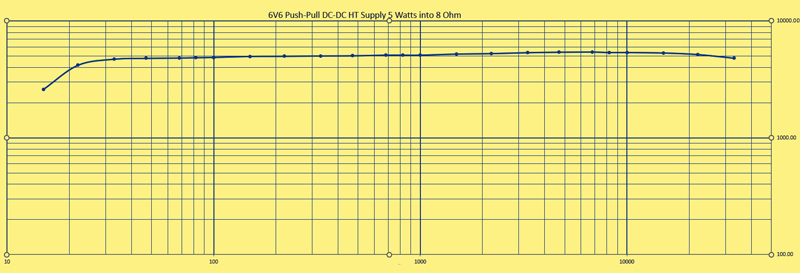
Power output at 4.2% THD.
The 6V6GT's used were a matched pair of new old stock valves branded Marshall. The current value on the valves was given as 31 mA. Not quite full spec.
Raising the HT voltage to 300 increases the maximum output to 6.6 Watts but significantly increase the current drawn. For most room settings this does not seem a worthwhile trade.
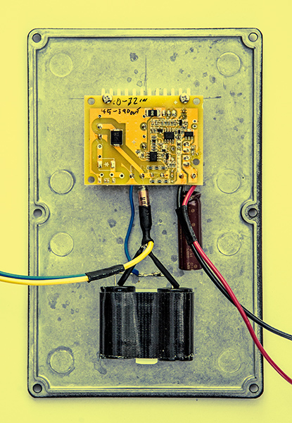
The HT power supply.
The HT power supply was built on the lid of the die-cast box that is used as the base of the amplifier.
The author was expecting to have to replace the module's heat-sink with a solid bar that could be tapped to take mounting bolts. However it was found that short M3 machine screws could be used as self tapping fixings in the same way that the heat-sink is held to the circuit board. The module runs cool and no heat-sink compound was used between module and lid.
The capacitor mounting seemed to be a problem as they had to lie flat to the metal and no suitable retainers were to hand and adhesive tabs were rejected due to the limited contact area on the 18 mm diameter cylinders. Some hard plastic (Delrin) rectangular section was sourced and cut to length. This was drilled and tapped for M2.5 machine screws. The capacitors were held to the block with linen lined adhesive tape.
Heat shrink sleeving covered the exposed leads and secured the input and output wires. The red insulation tape over the HT take-off point is not elegant - just effective. The underside of the module could be covered with an insulating sheet, but when secured in place there are no opportunities for touching the exposed contacts.
Initial testing of the amplifier revealed no background noise but when built into the box there was considerable noise. This was a buzzing sound and could possibly oscillation. Adding a 1,500 μF capacitor to the input of the module seemed to solve the problem but the buzzing returned.
The input DC connector was a chassis mounting 2.1 mm co-axial type. This was considered suspect and was removed and the input leads extended through the chassis and connected to the power supply externally. The amplifier returned to silence with the signal input shorted. Then the penny dropped: the chassis plug connected the input DC to the chassis and the switching noise was appearing in the ground loop.
Although the modules are non isolating and the ground is common to input and output, it is essential to keep the 19.5 Volt input leads separate from the output ground connection. The 2.1 mm connector was replaced with a three pin GX-12 aviation connector. A secure connector with provision for separate inputs to the heater converter and HT converter if required.
Initial testing had been with the bench power supplies and at 19.5 Volts the steady current was 1.4 Amps. Connecting a suitable laptop brick supply was a disappointment - the amplifier would not power-up. The initial in-rush current triggered the brick's overload circuit. A 24 V 2 Amp supply was no better. The third type tried was 19.5 V at 3.3 A and this was just adequate. Subsequent prolonged listening tests with this supply showed no problems. As suitable replacement laptop chargers were available from ebay a second one was purchased for the other channel.

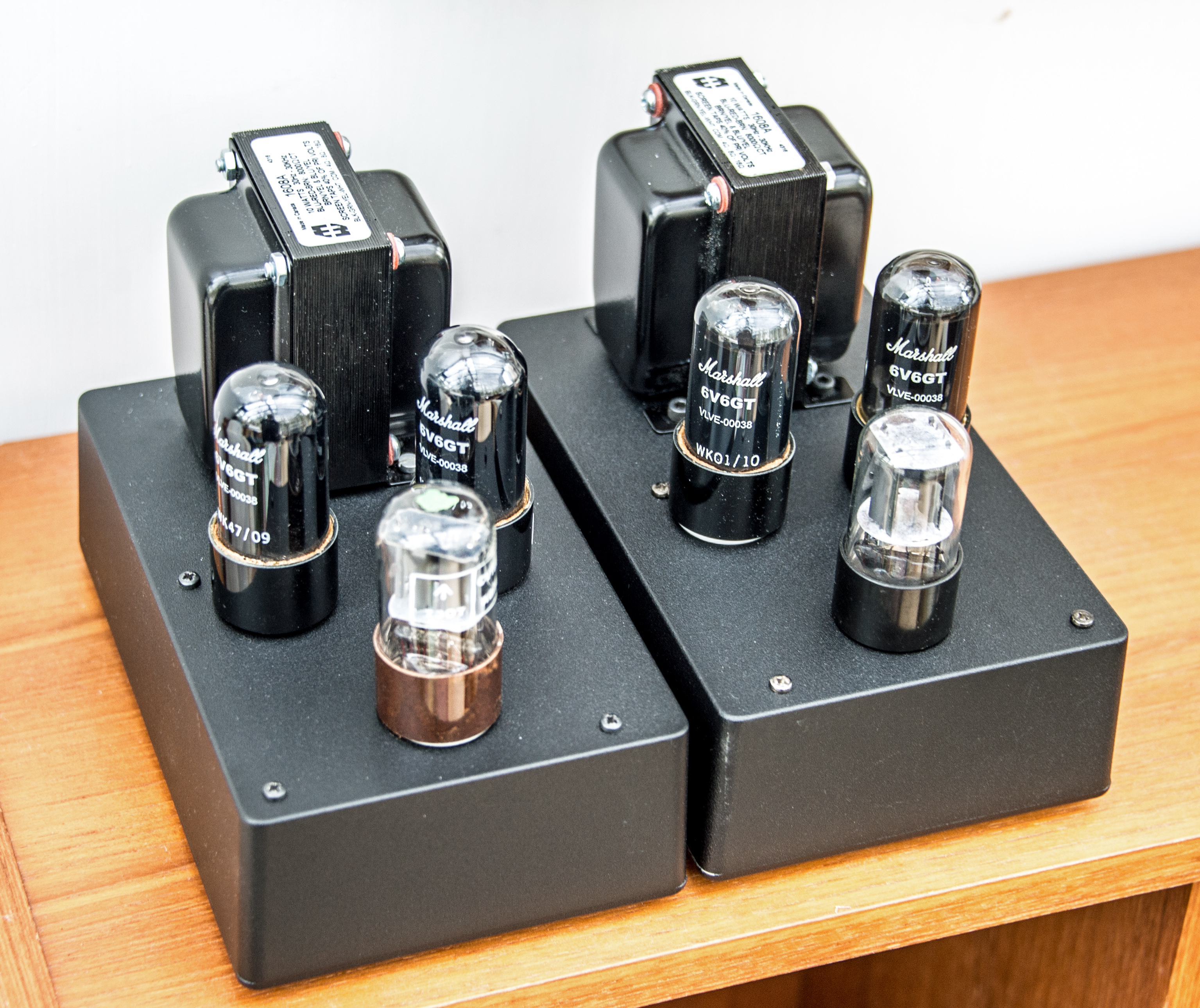
The completed stereo pair.
To avoid earth loops and hum the amplifiers are fed from separate laptop power supplies. The minimum requirement is 19.5 Volts at 3.3 Amps to cope with the surge of initial capacitor charging. Anything smaller and the over current protection prevents the amplifiers from starting.
Need help with essay writing? Try PapersOwl.
Postscript
Subjective evaluation of audio quality is always difficulty and open to bias both overt and subconscious. The author has been listening to music whilst working and not actively evaluating the audio. It came as a surprise that drum sounds seemed crisper than normal. Subsequent listening seemed to confirm the improvement in clarity over the Chinese 6V6 amplifier that had been in use for the past year. The differences in the two amplifiers are: Ultra-linear drive of the screen grids in the new amplifier and Hammond transformers not the unbranded Chinese output transformers. Both amplifiers are hum free with the new amplifier being driven by a constant voltage stabilised source.
|