|
A constant voltage source for laboratory and test Instruments.
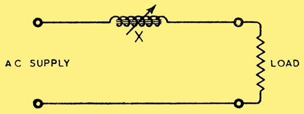
Fig. 1. Basic circuit of variable series impedance type of stabiliser.
The voltage stabiliser to be described belongs to what may be termed the 'variable series impedance' class. In Fig. 1, if the supply voltage varies, the voltage across the load may be kept constant by varying the reactance X. If, therefore, some means can be found to vary X automatically in sympathy with the variations of supply voltage, the voltage across the load will automatically remain constant.
It is well known that polarisation of the core of an iron-cored reactance or choke by means of DC in the winding will reduce. the reactance value. This is the principle used in the present apparatus. A simple choke, however, is not the best form of reactance to use, as it is difficult to get sufficient variation by means of DC, and the AC voltage across the choke would be applied to the DC circuit. A very effective arrangement is to connect two chokes in parallel, and provide separate windings for the DC. The DC windings are then connected in series-opposition, and no AC voltage is applied to the DC circuit. This arrangement is shown in Fig. 2 (a). It is simplified in Fig. 2 (b) by using a single winding for the DC, embracing both cores. In this case, one of the AC windings must be reversed.
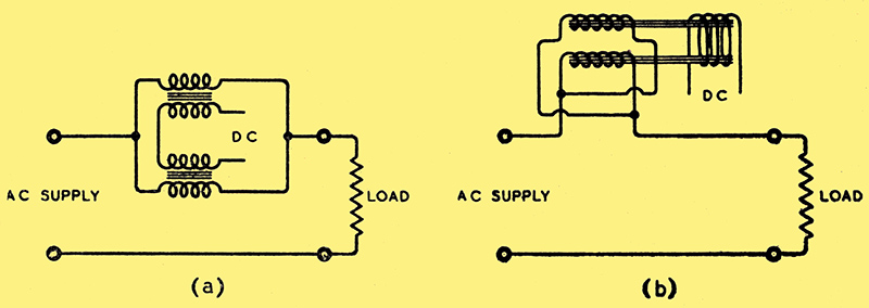
Fig. 2. Methods of eliminating AC from the DC windings of a polarised choke. (a) Separate chokes are connected in parallel with the DC windings in opposition. (b) A single winding is used for DC and the AC fluxes are in opposite phases.
The single DC winding has the advantage that a large number of turns may be used without high values of AC voltage being induced in any part of the winding. Where separate DC windings are used, as in Fig. 2 (a), although there is no resultant AC when the two windings are connected in opposition, the induced voltages across the separate windings may be very high. The variation of reactance obtainable with either of these twin-choke arrangements is much greater than that obtainable with a single choke.
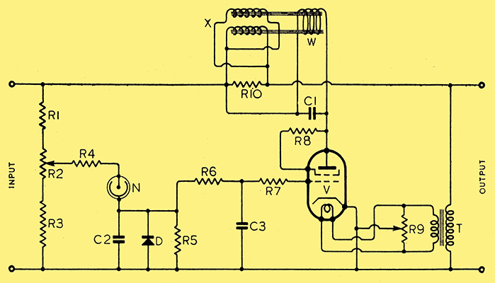
Fig. 3. Complete circuit diagram of AC stabiliser unit. R1, 7 kΩ; R2, 1 kΩ; R3, 12 kΩ; R4, 20 kΩ; R5, 30 kΩ; R6, 150 kΩ; R7, 250 kΩ; R8, 200 Ω; R9, 50-0-50 Ω; R10, 350 Ω. With the exception of R3, which should be rated at 2 Watts, all resistances may be of the 1 Watt type. C1, 8.0 &mu:F electrolytic; C2, 0.3 μF paper; C3, 0.5 μF paper; V, Osram KT41 tetrode, connected as triode; N, Philips 5 Watt neon lamp with cap resistance removed; D, half-wave metal rectifier, rating 20 V, 5 mA.
In arranging the DC supply it must be remembered that the reactance must be a minimum when the AC supply voltage is low, and must increase with increase of supply voltage. The DC must, therefore, be greatest when the supply voltage is low, and must decrease as the supply voltage rises. This requirement is readily met by utilising the anode current of a valve and arranging the negative grid volts to increase with increase of supply voltage. The complete circuit arrangement adopted is shown in Fig. 3. The resistance R10, in parallel with the choke, improves the performance by introducing a phase angle shift, and increases the power output.
Negative bias for the valve V is obtained by means of current through the neon tube N, the bias voltage being rectified and smoothed as shown. The anode current of V provides DC for the winding W on the reactance X. The DC is smoothed by the capacitor C1. Heater current for the valve is supplied by the transformer.
If the supply voltage variation is comparatively small, the primary winding of T may be connected across the input supply instead of the output as shown. This would result in a little more current being available for the output load. On the other hand, with the transformer connected as shown, it may be used as an output transformer with further secondary windings provided to give any value of constant output voltage required. It may be pointed out here, however, that the voltage will only remain constant with a definite value of watts loading. If different values of load are to be catered for, tappings may be provided on the reactance X, but a simpler alternative, when the connected load is less than that for which the apparatus is designed, is to add artificial loading to bring the total load up to the correct value. Such a method is not economical, of course, but that is usually of little consequence in the case of small test currents used for short periods.
Neon Control Circuit
The neon tube N is connected to a potential divider formed by the resistances R1, R2 and R3. R2 provides a fine adjustment of the neon tube voltage, and thus of the output volts. The resistance R4 limits the control exercised by the neon tube. If the value of R4 is too small, the neon control will be too great, and the output volts will fall appreciably as the supply volts rise; if R4 is too high, the reverse will be the case.
The potential divider is so proportioned that the neon tube just strikes when the supply voltage is a minimum. The operation of a neon tube in series with a resistance under conditions of varying voltage was described by the present writer in a previous article dealing with a DC voltage stabiliser [★] Constant voltage supply, Wireless World, February, 1942.. The conditions are not quite the same in the present case, where the supply is AC, and a capacitor forms part of the circuit, but the description mentioned will assist in understanding the operation.
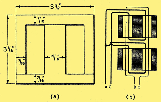
Fig. 4. (a) Dimensions of Stalloy stampings used in variable reactance unit and (b) arrangement of windings. The spacing of the two cores is determined solely by the depth of the AC windings.
The two cores of the reactance X were made of Stalloy stampings 0.014 in. thick, of the form and dimensions shown in Fig. 4 (a). Each core had an AC winding of 500 turns of 28 SWG enamelled copper wire, while the DC winding, embracing both cores, comprised 6,000 turns of 39 SWG double silk-covered copper wire. The windings were all on the centre limbs, the arrangement being shown diagrammatically in Fig. 4 (b). The cross-sectional area of each centre limb was 2 sq. in.
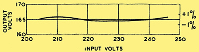
Fig. 5. Regulation curve of stabiliser with a load of 107 Watts.
The voltage characteristic with an output load of 107 Watts is shown in Fig. 5. It will be seen that the maximum variation from the mean output of 165 Volts is less than ± 0.5%. for an input voltage varying from 205 to 245 Volts. The output voltage may, of course, be altered as desired by the aid of suitable output windings on the transformer T. The test was made with a purely resistive load of 255 Ω connected to the same terminals as the primary of the transformer T, the voltage being 165 Volts. A heavier output load would require heavier cores and fewer AC turns for the reactance X, but the other details would remain the same.
Output Wave Form
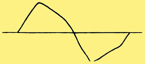
Fig. 6. Waveform of output voltage for an approximately sine wave input.
The wave form of the output voltage when the input voltage approximates to a pure sine wave is shown in Fig. 6. This output wave form is the same at all values of input voltage. Distortion of the input voltage wave form will alter the value and form of the output voltage characteristic to some extent. It is important, therefore, in plotting the output characteristic, to vary the input voltage by means of transformer tappings and not by means of variable resistances or impedances.
|