|
The early twenties was a period of turmoil and frustration for the De Forest interests. Seemingly endless lawsuits and patent litigation drained the resources of the Company and the time of its officers. RCA controlled the Fleming patents and had been granted an injunction which prevented De Forest from marketing triodes. Lee De Forest himself was involved in the development of Phonovision (sound movies) and was not active in the affairs of the De Forest Radio Telephone and Telegraph Company.
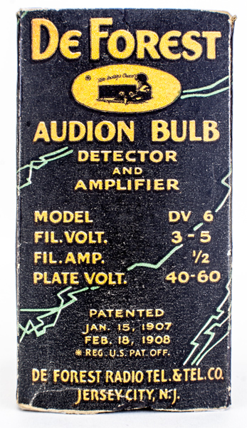
The Fleming patent expired in November of 1922, clearing the way for De Forest to once again manufacture Audions. The initial tubes advertised were the DV-1 and DV-6, first publicized in De Forest Catalogue K of early 1923. The V indicated a short pin or UV base while the number was the approximate filament voltage. The DV-6 was listed as having a 5 to 6 Volt thoriated filament drawing 0.5 amps. A cylindrical element structure mounted in a horizontal plane was employed. This valve was rather short and un-gettered (Fig. 1).
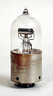
Fig.1. DV-6 detector/amplifier triode 1923. The DV-6 was introduced in early 1923, but by September of that year had been replaced by the DV-6A. The DV-6 did not have a paper label or any part number marked on the valve.
Tests run on a number of DV-6's indicate that the filament was basically straight tungsten and ran at a white heat. A DV-6 data sheet packed inside a tube carton gave a somewhat more accurate description of filament operation than Catalogue K. The sheet shows a filament voltage range of 3 to 5 Volts at 0.5 to 0.7 Amps. Several DV-6's tested drew about 0.75 Amps at 4 volts. These tubes can be found with two different styles of marking. The earlier version is marked 'PAT APL'D FOR' on the base and was etched De Forest in a circle around the top of the bulb. The later tubes are marked 'De Forest AUDION' with patent numbers on the base, and have no bulb marking. Neither tube has a type number marked. It is suspected that the earlier marked tube is actually the De Forest Type 20 sold by Moorhead in 1920, but this has not been verified.
The DV-1 was described as having a 1 to 1.5 Volt oxide filament drawing 0.2 Amps. This tube was described as having a horizontal structure. The filament was an oxide coated platinum type and was probably intended for use in WD-11 type applications. Although not specifically stated, it is assumed that a short bulb similar to the DV-6 was used. Adverts dated March 1923 gave essentially the same information, as well as several books published around that time. All of these sources illustrate the DV-6 only, no pictures of the DV-1 can be found. Somewhat later the DV-1 was advertised and described in a different form, a tall bulb with a 3.0 Volt filament. Samples seen of the DV-1 are normally the 3.0 Volt version (Fig. 2).
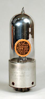
Fig.2. DV-1 Detector/ amplifier triode 1923. This valve was made only briefly and was replaced by the DV-3 in April of 1924.
De Forest may have decided that a '99 type tube was more commercially viable than a WD-11 type. The fact that the type number was not changed after the redesign to a 3.0 Volt tube was not inconsistent with the generally erratic marketing policies of the De Forest company. Several unmarked tubes have been seen which might be 1.0 Volt DV-1's. It should be noted that by early 1923 De Forest had sold his interest in the Radio Telephone and Telegraph Company and all references to De Forest pertain to the Company only.
The first adverts for the DV tubes to run in the major radio magazines appeared in September of 1923. The tubes described were the DV-1, DV-6A, and the DV-2. These tubes had nickel bases marked 'De Forest AUDION' and carried patent numbers along with a restrictive notice. The bulbs were gettered and had small round orange and black stickers with the type number. The DV-1 shown in Fig. 2 had a tall bulb and a 3.0 Volt thoriated filament. The electrical characteristic were similar to the UV199, and the tube was described as a 'Dry Cell Tube'. The DV-6A shown (Fig. 3) was an improved version of the earlier DV-6.
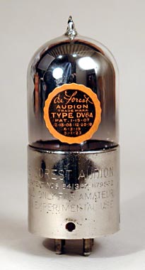
Fig.3. DV-6A Detector/amplifier triode 1923. The DV6A replaced the DV-6 and was only made from about September 1923 to April 1924.
The main structure was about the same, but a thoriated filament was used which reduced the current in half. The tube was gettered and was listed as a 'Universal Tube'. The DV-2 (Fig. 4) was a new addition to the series and had a 5 Volt 0.25 amp filament.
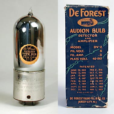
Fig.4. DV-2 detector/amplifier triode 1923. The base on the DV-2 was changed to Isolantite by April of 1924.
Although described as a 'Wet Cell Power Amplifier Tube', its essential characteristics were not much different than the UV201A. However, the recommended bias voltages for the DV-2 were lower than those of the '01A, resulting in higher plate current and somewhat lower plate impedance. Used in this fashion, the DV-2 was capable of slightly more output than an '01A but could hardly be considered as a power amplifier. Later De Forest data described this tube as a voltage amplifier and did not recommend its use as an output tube. These three tubes were packaged in conventional cardboard cartons. There is some evidence to suggest that the cartons contained an inner metal can of the type commonly seen for later De Forest tubes. However, pristine NOS samples have been examined which clearly did not use a metal can, so perhaps they came both ways.
In April 1924 new adverts showed major changes in the series. The use of metal bases was stopped in favour of new materials. The DV-1 and DV-6A were dropped, and the DV-3 was added. The DV-6A with its high filament current and low gm was not competitive with either the '99 or '01A, and was no doubt discontinued due to poor sales. The DV-1 was replaced by the DV-3, which had near identical performance. The DV-3, however, had a short bulb and horizontal element structure as opposed to the tall bulb and vertical structure of the DV-1. The first DV-3's used a Bakelite base (Fig. 5), the colour of which varied from maroon to dark brown.
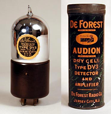
Fig.5. DV-3 (Bakelite) detector/amplifier triode 1924. The DV-3 was made with a Bakelite base from about April 1924 to late 1925.
Moulded into the base was a round logo which was nearly identical to the paper sticker except for the omission of the type number. The DV-2 was retained but the base was changed to Isolantite (Fig. 6), a ceramic material with excellent electrical properties.
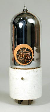
Fig.6. DV-2 (Isolantite) detector/amplifier triode 1924. From about April 1924 to October 1924 the DV-2 used an Isolantite base. Some of these tubes had smooth glazed bases. This early Isolantite version can be identified by the use of the small round paper label.
Early DV-2 Isolantite bases often have a somewhat rough texture, and some have tool marks as though they were turned on a lathe. Some of these early bases had a glazed outer coating which generally turns a slight yellowish colour. The first DV-2's had a stamped circular logo on the base similar to the moulded markings on the DV-3. This logo was used only briefly and then modified by adding the wording 'Isolantite-bases mfg for excl' above the circle.
De Forest sales brochures of the period describe the DV-2 and DV-3 as having Yttrium or Yttriated filaments. Since General Electric controlled the thoriated tungsten patents, it is not surprising that De Forest resorted to other materials. The expiration of the De Forest triode patent in early 1925 brought forth a flood of independent valve makers into the market and the general use of thoriated filaments. No mention of Yttrium is made for other De Forest tubes.
November of 1924 brought several changes. The company had been reorganized and was now known as the De Forest Radio Company. The base of the DV-2 was changed from Isolantite to Bakelite (Fig. 7).
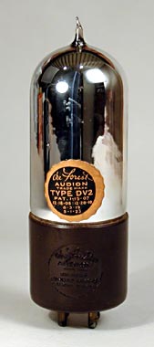
Fig.7. DV-2 (Bakelite) detector/amplifier triode 1924. The DV-2 used a Bakelite base from about October 1924 through late 1925.
The moulded logo was the same as used on the DV-3 and the paper sticker was unchanged. The Bakelite bases were used on the DV-2 and DV-3 into 1925 but by the end of that year had been switched to Isolantite. See also DV-3.
1925 saw the introduction of two new tubes to the series and also a new label. The DV-3A (Fig. 8) was the first of these new tubes and was electrically the same as the DV-3 but had a smaller base which was compatible with the standard '99 socket.
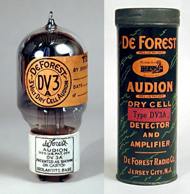
Fig.8. DV-3A detector/amplifier triode 1925. The DV-3A used a base compatible with the standard UV199 and had similar characteristics.
The base marking was changed to a square format and included the DV-3A type number. This was the only tube in the series to have the type number on the base. The small round sticker used on the earlier types was replaced with a larger label which wrapped half way around the valve. This label gave the tube number, filament voltage and general function of the tube. This label was used on all new types and only the DV-2 and DV-3 can be found with either the round sticker or large label. The other new tube of 1925 was the DV-5 (Fig. 9).
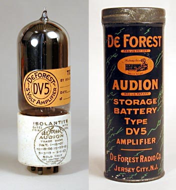
Fig.9. DV-5 audio amplifier triode 1925. The DV-5 was used mainly as an audio amplifier and had greater output capability than the DV-2.
The DV-5 was used mainly as an audio amplifier and had higher ratings than the DV-2. The DV-5 was particularly useful as a driver for an power output tube. Our DV-5 came with can and paper leaflet.
Next to appear was the DV-7 output tube (Fig. 10), released in late 1925 or early 1926.
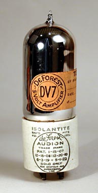
Fig.10. DV-7 audio output triode 1926. The DV-7 was used as an output tube but had only about half the output capability of a UX112.
This valve had a 5 volt 0.5 amp filament and was intended for use in the last audio stage only. Despite the higher filament current the DV-7 was only capable of about 70 mW of output, not much more than an '01A operating at the same plate voltage of 135 Volts. The UX-112, which appeared about the same time, was good for almost twice the output of the DV-7 at the same operating voltages.
In July of 1926 the DV-9 was announced (Fig. 11) More details here.
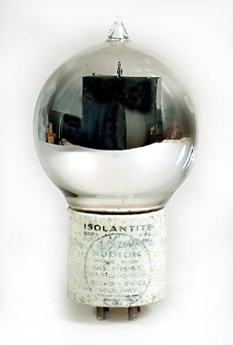 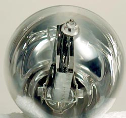
Fig.11. DV-9 low power transmitting triode 1926. The DV-9 was intended for transmitting use only and has a somewhat different internal design than the later DL-9. This tube was made only briefly before being replaced by the Type D transmitting tube.
The DV-9 was a transmitting tube with a 7.5 Volt AC filament and used a spherical bulb. This tube is rarely seen, and the few samples known have no marking other than the standard De Forest logo on the base. The operating conditions are unknown. This tube was apparently replaced the next year by the type D transmitting tube. A companion rectifier, the DV-9R was announced in the same advert as the DV-9. No specifications are available for this rectifier, and it is seen even less frequently than the DV-9. It appears to have been replaced in 1927 by the DR.
The DL series was introduced in 1926. The DL tubes had long pins and the then new UX base. Four DL tubes appeared in 1926 but only one was really a new design. This new tube was the DL-4 (Fig. 12), intended for use as an RF amplifier.
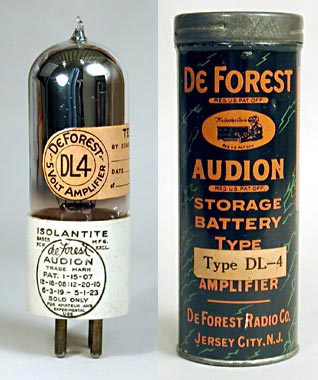
Fig.12. DL-4 RF amplifier/oscillator triode 1926. The DL-4 was a special purpose tube intended only for service as an RF amplifier or oscillator. This tube could also be used as an IF amplifier in early superhets.
The DL-4 had higher gm and lower grid-plate capacitance than an '01A and gave improved performance with weak signals when used in RF stages. This tube was also recommended for use as an oscillator in superhet receivers. The other tubes released that year were the DL-2, DL-5, and DL-7 (Figs. 13, 14, 15).
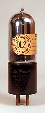
Fig.13. DL-2 (Bakelite) detector/amplifier 1926. The DL-2 was made with a black Bakelite base in 1926 but by 1927 had an Isolantite base.
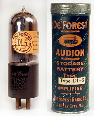
Fig.14. DL-5 audio amplifier triode 1926. The DL-5 was made with a black Bakelite base in 1926 but by 1927 had an Isolantite base.
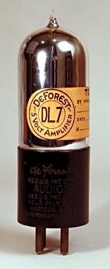
Fig.15. DL-7 (Bakelite) DC audio output triode 1926. The DL-7 was made with a black Bakelite base in 1926 but by 1927 had an Isolantite base.
These tubes were identical to their DV counterparts except for the base. During 1926 these types were made with black Bakelite bases, but by 1927 had been changed to Isolantite.
1927 brought the last four tubes of the DL series onto the market. The DL-3 was a UX based DV-3 (Fig. 16), but the other types were all new designs.
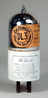
Fig.16. DL-3 detector/amplifier triode 1927. The DL-3 was the same as the DV-3 but had a UX base.
The DL-14 was a medium power audio output tube with low output impedance (Fig. 17).
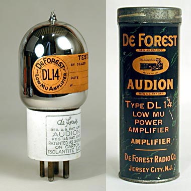
Fig.17. DL-14 DC audio output triode 1927. The DL-14 was an output tube similar to the UX171.
This tube had the same recommended plate and grid voltages as the '71A, but had a somewhat higher plate impedance. The DL-14 had a max output of about 630 mW while the 71A would produce about 700 mW. A larger bulb was used on the DL-14, the same size and style as used on the earlier Moorhead VT. During 1927 the DL-7 was modified to use this same larger bulb (Fig. 18).
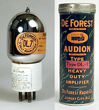
Fig.18. DL-7 DC audio output triode 1927. The DL-7 bulb type was modified in 1927 to the larger size used on the DL-14.
Another power tube brought out that year was the DL-9. This tube had a max output of about 2 Watts, somewhat more than a '10 which would produce about 1.6 Watts. The DL-9, however, required a 500 Volt anode supply and had a rather low gm for a power tube. The DL-9 probably had limited usage due to the introduction in early 1928 of the '50. Under similar operating conditions the '50 had almost 2.5 times the output power and required less filament current.
The last tube in the series was the DL-15, designed for use as a detector (Fig. 19).
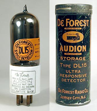
Fig.19. DL-15 DC detector triode 1927. The DL-15 was an alkali vapour detector tube, similar to the UX200A.
This valve had a rather high μ and gm, much like the '00A. De Forest data sheets claimed superior results for the DL-15 when working with weak signals. To test these claims a special test circuit was built up using lab equipment. The circuit itself consisted of a basic grid leak detector stage in a well shielded enclosure so that operation at low signal levels could be checked. Several DL-15 tubes were tested and found to have consistent but disappointing performance. As a low level detector, the DL-15 was about equal to an '01A and much less efficient than an '00A. The internal construction of the DL-15 strongly suggests that like the '00A it was a caesium vapour tube. Unlike other brands of '00A's, the DL-15 had a silver coloured getter. It may be that some reaction took place between the getter material and the caesium over time which reduced the effectiveness of the tube. There must have been some valid technical reason for other manufacturers to not silver getter their '00A's.
With the advent of the DL series in 1926 all new types introduced after that time were made with the DL base only, thus the DL-4, DL-9, DL-14, and the DL-15 do not have DV counterparts. However, the earlier types were marketed with both base styles through 1927. The Isolantite base versions of the DL-2, DL-5, and DL-7 appeared in 1927 and are shown in Figs. 20, 21, and 22.
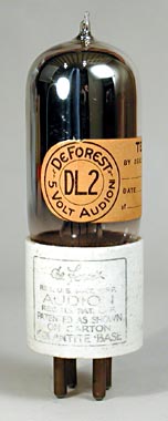 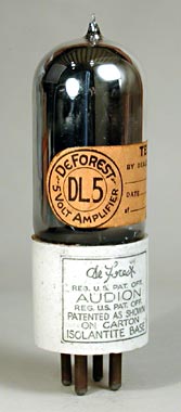 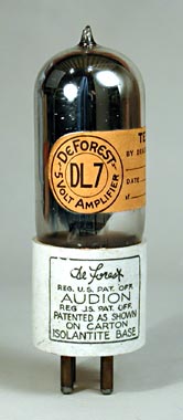
Fig.20-22. DL-2 det/amp triode 1927, DL-5 DC AF amp triode 1927 & DL-7 DC output triode 1927.
The author has a large De Forest advertising sheet of 1927 which shows that the entire series, including the DV types, were all available at that time. This listing does not include the DV-1, DV-6 or DV-6A which were dropped in 1924. The DV-DL tubes were phased out in 1928 with the appearance of the D400 series. This new series used industry standard numbers (like D400A) and had Isolantite bases.
Note that the number DV-8 was apparently skipped, likewise these is no known DL-8. The numbers 10 through 13 were also not used, but this was to be expected. Tube types '10 through '13 had already been issued by RCA, and De Forest would have avoided using these to make his designations unique. Type 8 had not been used at this time (later used by Philco for a ballast tube) so the reason for it not being issued by De Forest is unclear. Perhaps this designation was used for a prototype that never made it to production.
Published technical data for the DV-DL tubes is scant, and even De Forest data sheets seldom gave more than the recommended operating voltages. Due to this situation the following table of characteristics was generated. Most of this information came from publications like Enno Hann's Radio Trouble Shooting and other generally obscure sources. No published data was found for types DV-1, DV-6 or DV-6A. Data for these types was obtained by testing a number of tubes of each type at the De Forest recommended operating conditions. The results were averaged for the table. Published data for the DV-2, DV-3, and DV-5 differed considerably from tests run on five or more samples of each, and the table data is based on those tests.
Type | Vf | Af | Va | Vg | mAa | ra | μ | gm |
DV-1 | 1-1.5 | 0.2 | 40-60 | - | - | - | - | - |
DV-1 | 3.0 | 0.07 | 67.5 | -1.5 | 2.6 | 16k | 6.4 | 0.4 |
DV-2 | | | | | | | | |
DL-2 | 5.0 | 0.25 | 90 | -1.5 | 4.8 | 9.6k | 8.0 | 0.83 |
DV-3/A | | | | | | | | |
DL-3 | 3.0 | 0.06 | 90 | -4.5 | 2.7 | 15.7k | 6.6 | 0.42 |
DL-4 | 5.0 | 0.25 | 90 | -4.5 | 5.3 | 7.8k | 9.0 | 1.15 |
DV-5 | | | | | | | | |
DL-5 | 5.0 | 0.25 | 135 | -3.0 | 6.9 | 9.7k | 9.7 | 1.0 |
DV-6 | 4.0 | 0.74 | 60 | -1.5 | 1.0 | 30k | 8.1 | 0.27 |
DV-6A | 4.0 | 0.36 | 60 | -1.5 | 1.4 | 23k | 7.4 | 0.32 |
DV-7 | | | | | | | | |
DL-7 | 5.0 | 0.5 | 135 | -9.0 | 6.0 | 6.5k | 7.0 | 1.1 |
DV-9 | 7.5 | 1.0 | - | - | - | - | - | - |
DV-9R | - | - | - | - | - | - | - | - |
DL-9 | 7.5 | 1.6 | 500 | -51 | 35 | 6.0k | 6.5 | 1.083 |
DL-14 | 5.0 | 0.5 | 180 | -40.5 | 15 | 2.6k | 3.0 | 1.1 |
DL-15 | 5.0 | 0.25 | 45 | To f+ | 3.9 | 23k | 17 | 0.725 |
|