|
Another Boyuu amplifier from Chinese supplier Douk. This amplifier was sold at £183.00 with £26.00 post and packing.
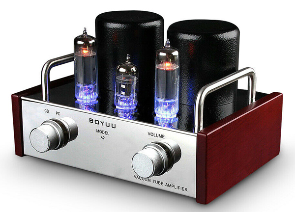
The top image from the ebay listing.
The parallel pair EL84 mini amplifier was a big disappointment. Would this amplifier be a good choice for an office or small room?
The advert gave the following details:
- Input sensitivity: 550 mV
- Power output: 2C3.6 W
- S/N ratio: 84 dB
- Input Jacks: stereo RCA
- Input impedance: 100 KΩ
- Output impedance:4 & 8 Ω
- Power supply: 100 V-240 V & 50 Hz/60 Hz
- Power consumption: 45 W
- Frequency response: 38 Hzb36 KHz
- Vacuum tubes: 12AX7 x 1, 6P14/EL84 x 2
- Dimensions(W*D*H): 220x188x136 mm
- Net weight: 4.0 Kg
- Package weight: 6.0 Kg
What the advert does not say is what percentage distortion you get at 3.6 Watts per channel and how many dB down on peak response the high and low response figures given are.
The amplifier arrived in a substantial cardboard box wrapped in parcel tape. After three days quarantine the box was opened to reveal the amplifier held between two plastic foam end cheeks. This was the most professional packing yet seen on Douk products. It gave a good feeling about the product from the start.
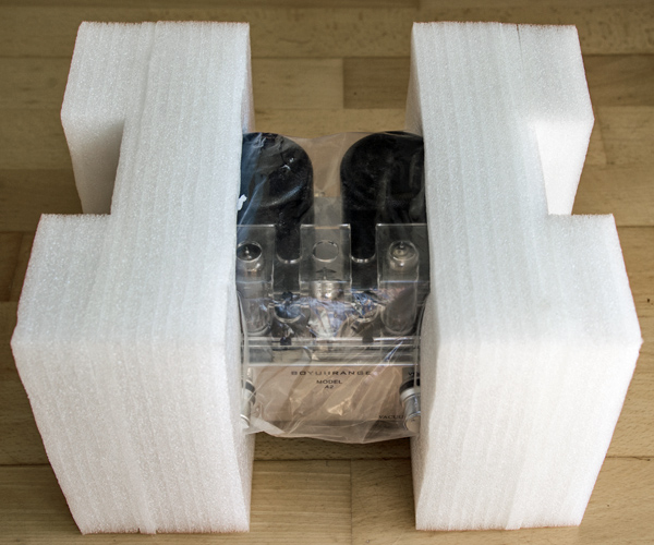
Straight out of the cardboard box.
The protection afforded by the end cheeks had protected the amplifier perfectly. The end packing was removed and the amplifier was further dust proofed by a poly bag.
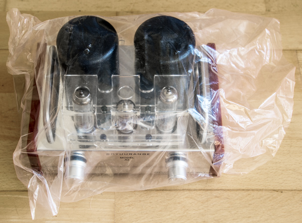
Protected by a polythene bag.
The mains lead supplied had a UK mains plug. Earlier amplifiers came with a two pin plug and adapter. This lead was to full UK specification for consumer electronics.
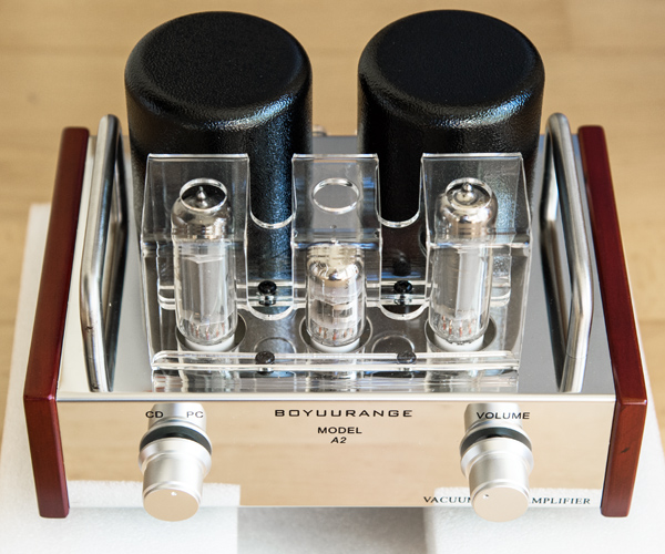
The new amplifier.
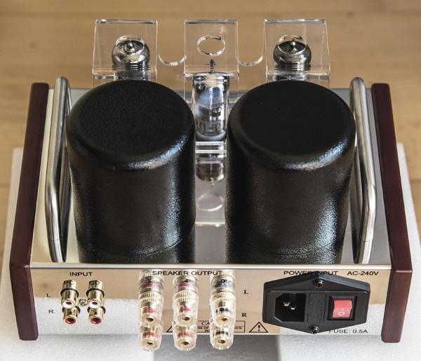
The rear connections.
The images of the amplifier as supplied match exactly the amplifier originally advertised. The only exception to a regular consumer product was the complete absence of documentation. However, all relevant information about performance was contained in the advert. For a consumer product it should have had warning about no user serviceable parts inside, do not cover and that the valves can burn when operating. Nit picking but important for a mass market product.
The amplifier was unpacked in the writer's house and so it was simple to connect the amplifier to the Danish Jamo speakers in the lounge and listen to the sound without any prior knowledge of actual technical performance.
A range of music was played from deep organ bass to classical piano and modern popular music and, of course, Pink Floyd. The volume was never set above comfortable and the sound was pleasing at this level. The Bach Toccata played with the full bass range but not room shaking bass. So far a good amplifier and one that fitted with the room
Testing
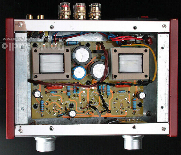
The under chassis image from ebay.
The bottom cover seems to have been fitted with air tools as the screws took a lot of force to move. A clear sign of production line assembly. Within the only difference from the advert was the layout of the AC wiring. The amplifier is built on a single double sided PCB and well made. The small output transformers mount directly on the board. The black cylinders above the chassis are the two mains transformers - HT and heater. The heaters are run from a 6.3 Volt supply as expected. The HT transformer outputs 230 Volts. In the image these are the brown wires.
The output transformers have three secondary connections that are taken to the rear sockets. The secondaries are not returned to ground and there is no provision for negative feedback.
At the centre of each valveholder is a blue LED. These are supplied from the heater line via a half wave rectifier and a limiting resistor. The clarity of the board allowed the circuit to be traced without difficulty.
The amplifier was connected to dummy loads and powered-up so that voltage measurements could be made.
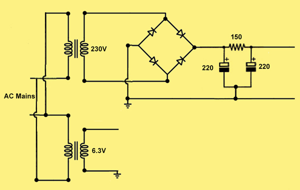
The power supply circuit diagram.
The heater circuit is AC with one side grounded. For the HT, the AC from the mains transformer is rectifier by a bridge rectifier, the black rectangle to the left of the right output transformer, and passed to a 220 μF 400 V reservoir capacitor. On load the voltage on the reservoir is 295 V. A smoothing filter consisting of a 150 Ω resistor and a second 220 μF 400 V capacitor generates the main HT rail of 286 Volts. A further filter of a 50 kΩ resistor and capacitor feeds the voltage amplifiers. The value of the capacitor, seen blue in the image, was not seen. This rail is at 213 Volts. The filtering is quite adequate as no hum has been detectable at normal listening distance in a quite room.
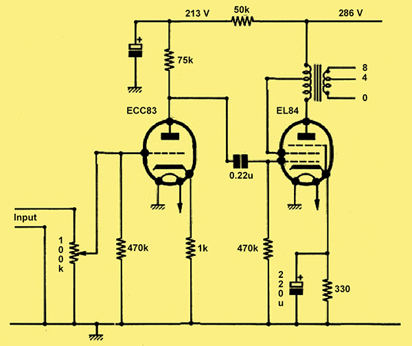
The amplifier circuit diagram.
The circuit is a simple voltage amplifier triode with un-bypassed cathode feeding the output valve through a 0.22 μF 400 V capacitor of good quality. The only feedback is the local path around the EL84 given by the screen grid tapped into the output transformer.
The output transformers are small, much smaller than the Partridge transformer used in the Mullard 3-3 amplifier. A consequence of a low iron content is a limited bass response.
The anode of the ECC83 is at 145 volts and a cathode current of 1.0 mA is used - quite normal. The EL84 cathode bias is formed via the 330 Ω resistor and was measured at 9.53 Volts. That gives a standing cathode current of 29 mA. The anode was measured at 277 Volts and the screen at 281 Volts. The DC input to the output stage is under 8 Watts. Full rating for the EL84 is an anode dissipation of 12 Watts. A rough guide for a SE output stage of this type is an efficiency of 33% or 2.67 Watts output.
The amplifier was connected to 8 Ω non inductive resistors and both input channels connected in parallel to the function generator. The output was measured on the Tektronix 'scope including THD via the FFT display and measurement.
At 1 kHz sine wave the output was increased to give 3.5 Watts (5.23 V RMS) across the load resistors. The waveform was badly distorted and a figure of 18% THD recorded. This would be highly unpleasant to listen to. The output was then adjusted by trial and testing to achieve a THD of close to 10% - the classic level of maximum distortion for an audio amplifier.
4.11 V at 1 kHZ produced a figure of 10.6% THD. The input was then 290 mV. This gives an output power of 2.1 Watts. Correcting for sine wave testing of a cathode biased amplifier gives an output of 2.3 Watts RMS.
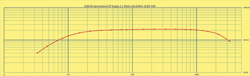
The response curve.
The curve above conveniently places the -3 dB points on the 1 Watt thick line. This gives a response of 70 - 30 kHz. The lower end is what the size of the output transformers suggests. The curve would be flatter with negative feedback but this would require more overall open-loop gain.
Conclusion
As a study/desk amplifier it is a good product well made and offers more than adequate volume. Good value for the price and a good looking piece of consumer audio. The acrylic cover for the valves also provides a measure of protection against little fingers getting burned.
That this was not going to offer Hi-Fi to the degree the advert said was evident in the parameters not given in the specifications.
This amplifier looks the part and will stay connected to the Jamo speakers in the main living room. The writer mainly listens to music in the garden office where push-pull 6V6's drive Wharfedale speakers. This amplifier has much iron and consequently looks bulky - too bulky to be allowed into the main lounge.
|