|
The following recommendations have been based on the British Standard Code of Practice CP1005: Parts 1 and 2, 1954, 'The Use of Electronic Valves'.
1. Definitions of Rating SystemsUnless otherwise stated, all limiting values given in the Mullard Technical Handbook are in accordance wih the design-centre rating system. The design-maximum and absolute-maximum rating systems may be used in certain circumstances. The following definitions of these three rating systems are based on those agreed by the International Electrotechnical Commission:-
1.1 Design-centre rating systemDesign-centre ratings are limiting values of operating and environmental conditions applicable to a bogey valve of a specified type as defined by its published data, and should not be exceeded under normal conditions. These values are chosen by the valve manufacturer to provide acceptable serviceability of the valve in average applications, taking responsibility for normal changes in operating conditions due to rated supply voltage variation, equipment component variation, equipment control adjustment, load variation, signal variation, environmental conditions, and variations in the characteristics of all electron devices in the equipment. The equipment manufacturer should design so that initially no design- centre value for the intended service is exceeded with a bogey valve in equipment operating at the stated normal supply voltage. A bogey valve is one whose characteristics have the published nominal values for the type. For a bogey valve for any particular application, only those characteristics which are directly related to the application need be considered
1.2 Design-maximum rating systemDesign-maximum ratings are limiting values of operating and environmental conditions applicable to a bogey valve of a specified type as defined by its published data, and should not be exceeded under the worst probable conditions. These values are chosen by the valve manufacturer to provide acceptable serviceability of the valve, taking responsibility for the effects of changes in operating conditions due to variations in the characteristics of the valve under consideration. The equipment manufacturer should design so that initially and throughout life no design-maximum value for the intended service is exceeded with a bogey valve under the worst probable operating conditions with respect to supply-voltage variation, equipment component variation, equipment control adjustment, load variation, signal variation, environmental conditions and variations in characteristics of all other electron devices in the equipment.
1.3 Absolute-maximum rating systemAbsolute-maximum ratings are limiting values of operating and environmental conditions applicable to any valve of a specified type as defined by its published data, and should not be exceeded under the worst probable conditions. These values are chosen by the valve manufacturer to provide acceptable serviceability of the valve, taking no responsibility for equipment variations, environmental variations, and the effects of changes in operating conditions due to variations in the characteristics of the valve under consideration and all other electron devices in the equipment. The equipment manufacturer should design so that initially and throughout life no absolute-maximum value for the intended service is exceeded with any valve under the worst probable operating conditions with respect to supply voltage variations, equipment component variation, equipment control adjustment, load variations, signal variation, environmental conditions, and variations in characteristics of the valve under consideration and of all other devices in the equipment.
2. Interpretation of design-centre ratingsWhen the circuit designer uses the design-centre system he should realise that the valve manufacturer takes into account the effects of normal random variations in conditions and components and assumes that normal good practice is followed in the design and use of components. No allowance is made for discrete changes in conditions or components.
2.1 Rated supply voltage and its variationIn equipment which is to operate from the normal supply mains a voltage tap should be provided for every declared mains voltage. Where this is not practicable however, and two or more declared voltages are covered by one tap, compliance with the design-centre system must be checked on the highest and lowest declared voltages in each tap. For the purpose of checking, all devices must be bogey. If the equipment is checked in this way and the designer has complied with all other relevant sections in these recommendations the equipment can be operated from a supply that has normally-encountered voltage variations of up to 110%. (The normal ratio of power variation to voltage variation of approximately 2 : 1 is assumed. If the ratio is greater than 2 : 1 in a particular circuit, the maximum permissible dissipation at which any valve can operate must be reduced accordingly below the limiting value.) Where a valve is recommended solely for low voltage operation (as in the car-radio range) allowance has already been made for the variations in accumulator voltage, which can be greater than 10%. For further recommendations see section 3.1.5. For valves intended for operation from dry batteries where the relevant maximum battery voltage is quoted under limiting values, due allowance has already been made for the fact that the battery terminal voltage is higher for a new battery and falls during life. For mains operation, the maximum battery voltage quoted under limiting values should be taken as the limiting value on the design centre system. For further recommendations on battery and battery-mains operation of filamentary valves see section 3.2.
2.2 Equipment components and their variationsIn an equipment the operation of any one component is to some extent dependent on every other component in that equipment. It is good practice to use self bias, such as provided by a cathode resistor or grid current bias (see section 5.3), rather than fixed bias. When this is done, further components can be added as long as the added variations are not large compared with those already existing, as in general the addition of a component to a circuit reduces the effects of the variations of the other components already in that circuit, besides adding the effect of its own variations. If a power valve or high-slope valve is operated within 20% of its maximum dissipation rating, a 110% tolerance cathode-bias resistor should be used. If a cathode-bias resistor cannot be used, then with a pentode or other multigrid valve a screen-grid dropping resistor having a 110% tolerance should be incorporated (see section 5.4). Similarly, with a triode a dropping resistor should be used in the anode circuit (see section 5.6). Valves should not be used in circuits where their operating conditions are dependent on another circuit or valve, unless the more important transferred variations are small compared with the variations in the operating conditions. When two valves are used in push-pull, for example, separate cathode-bias resistors should be used.
2.3 Equipment control adjustmentThe valve manufacturerbs responsibilities do not include conditions produced by gross maladjustment of controls which result in incorrect operation of the equipment. When a pentode or other multi-grid valve is used under conditions where the equipment control adjustment affects the valve operating conditions, special attention must be paid to the screen-grid operating conditions (see section 5.4). ln equipment which has multiple functions (e.g. transmitter/receivers, TV/FM receivers, etc.), it is assumed that the valves are used within their ratings in all modes of equipment operation.
2.4 Load variationThe valve manufacturer takes responsibility for the changes in valve operating conditions which are caused by the normal random variations of any component connected externally as a load, provided that normal good practice has been followed in the design and use of the component. Where definite changes occur in the load, all ratings should be checked at the worst long period running condition.
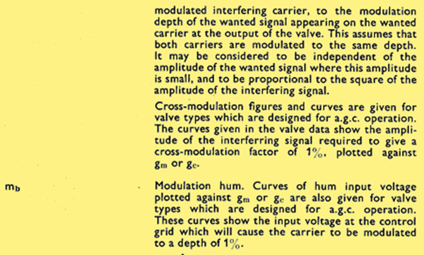
2.5 Signal variationThe valve manufacturer accepts responsibility for changes in the operating conditions due to random variations in signal (fading etc.) but not due to discrete changes (switching, or tuning to stations of varying strengths). When AGC is used, the operating conditions of the valves will change with the strength of signal received. The operating conditions of all the stages (controlled and uncontrolled) must therefore be checked under their worst long period running conditions.
2.6 EnvironmentIt is good practice to ensure that the bulb and base temperatures are kept low. They should not exceed the published limiting values in the environment for which the equipment is designed. Where equipment may be run under more than one condition it should be checked at each condition. If the maximum temperature ratings are not given on the data sheet of the valve in question, see Fig. 1 (Appendix III). Care should be taken to ensure that the minimum pressure in the environment for which the equipment is designed is not less than the published limit. In general, B7G and B9A based valves can be used at pressures down to approximately 50 mm Hg (that is up to altitudes of about 60,000 ft). The manufacturer's advice should be sought if it is desired to operate octal-based valves at pressures below 525 mm Hg (that is above altitudes of about 10,000 ft).
2.7 Other electron devicesThe valve manufacturer takes responsibility for changes in operating conditions caused by the variations in the characteristics of all other electron devices in the equipment, provided that normal good practice has been followed in the use of each electron device, i.e. variations are not large compared with those already existing.
3. Heater and Filament Ratings
3.1 Indirectly heated valves
3.1.1 Parallel operation (mains supply)The heater voltage of individual valves must be within ±7% of the rated value (unless otherwise stated) when the supply voltage is at its nominal value, and valves with bogey heater characteristics are employed. This variation is normally dependent upon more than one factor. The total variation may be taken as the square root of the sum of the squares of the individual variations arising from the effects of the tolerances of the separate factors, provided that no one of these deviations exceeds ±5%. If a tap is used for more than one input voltage (as provided for in paragraph 2.1) the heater voltage of each valve must be checked on the highest and lowest declared voltages covered by the tap and should be within ±4% of the rated value.
3.1.2 Series operation (mains supply)The heater current of series connected valves should be within ±3.5% of the rated value when the supply voltage is at its nominal value, and valves with bogey heater characteristics are employed. This variation is normally dependent upon more than one factor. The total variation may be taken as the square root of the sum of the squares.of the individual variations arising from the effects of the tolerances of the separate factors, provided that no one of these variations exceeds ±2.5%. lf a tap is used for more than one input voltage (as provided for in paragraph 2.1) the heater current must be checked on the highest and lowest declared voltages covered by the tap and should be within ±2% of the rated value. In applications where a wide variation in the dynamic characteristics of the valve is acceptable, as for example in simple AM broadcast receivers and low-cost amplifiers, the heater current tolerance may be increased from ±3.5% to ±5%. This allows for the use of three taps to cover the range 200 to 250 V even in applications where the chain consists mainly of a dropping resistor. lt is permissible for the heater voltage to rise to a maximum value 50% in excess of the nominal rated value during switching and the warming-up period when using valves with nominal heater characteristics, unless otherwise stated.
3.1.3 Pulse and RF operation of heatersWhen a valve heater is operated from a pulse or RF supply, special care should be taken to ensure that the correct power is delivered to the heater and that the peak voltage across the heater is not excessive. ln many rectifier applications, the valve will be required to supply only small currents. ln these cases a relaxation of the normal ±7% heater voltage tolerance is allowed for some valve types. Details of the permissible relaxation are given on the appropriate data sheets.
3.1.4 Fluctuations in mains supply voltageIn addition to the tolerances quoted in 3.1.1, 3.1.2 and 3.1.3 above, fluctuations in the mains supply voltage not exceeding ±10% are permissible. These conditions are, however, the worst which are acceptable, and it is better practice to maintain the heater as close to its nominal rating as is possible. Closer adherence to the rated heater voltage or current produces optimum valve life and performance.
3.1.5 Parallel, series or series-parallel operation from accumulatorsWhen valve heaters are supplied in parallel from a 6.3V "on charge" accumulator, a resistor must be included to make up the difference between the heater voltage and the "on charge" battery voltage of 7 V. When valve heaters are supplied from an accumulator and are connected in a series-parallel arrangement, as is common for mobile operation, equalising bars should be used: that is, the points in the parallel chains which are at equal potential should be interconnected. It is necessary to have at least two, and preferably three, heaters connected in parallel in the resulting series-parallel arrangements, so that the variations are reduced to those which are expected with parallel operation. If this is done, up to four 6.3 V valves can be connected in series and fed from an "on charge" 24 V accumulator, or two from a 12 V accumulator, provided that a resistor is included to make up the difference between the total heater voltage and the nominal "on charge" battery voltage. The nominal "on charge" battery voltages may be taken as 28 V and 14 V respectively. If it is then required to operate from an accumulator that is not on charge, e.g. under emergency conditions, the equipment designer must ensure that his circuits will operate satisfactorily with any valves of the types in question, both when new and throughout life. It is suggested that the series dropping resistor should be switched out of circuit during "off charge" operation. The advice of the valve manufacturer can be sought on any specific points. Where life and reliability are of particular importance, with a series-parallel heater arrangement the supply voltage variation should be kept to a minimum, preferably less than ±2%.
3.2 Filamentary valves
3.2.1 Parallel operation
3.2.1.1 1.25 V filamentary valvesValves with 1.25 V filaments are designed to be operated from a dry cellwith a rated terminal voltage of 1.3 V. The lowest filament voltage at whichthe valve may be expected to operate satisfactorily is approximately 1.0 V.If these valves are operated from dry cells with a rated terminal voltageof 1.5 V, a suitable dropping resistor must be used.
3.2.1.2 1.4 V filamentary valvesValves with 1.4 V filaments are designed to be operated from a dry cell with a rated terminal voltage of 1.5 V. The lowest filament voltage at which the valve may be expected to operate satisfactorily is approximately 1.1 V.
3.2.2 Series operationValves with 1.4 V filaments may be used with their filaments in series.Valves with 1.25 V filaments are not recommended for this form ofoperation.
3.2.2.1 Operation from dry cellsIf valves with 1.4 V filaments are operated with their filaments in series from dry cell batteries, shunting resistors will be required to by-pass sufficient cathode current to ensure that the correct filament current flows in the chain. In order to calculate the required value of shunt resistor the division of cathode current between the two filament limbs must be known or determined by measurement. In equipment which has separate HT and LT batteries, the question of battery replacement must be considered. If the bias for the output valve is not made independent of the LT battery, large variations can occur in the cathode current of the output stage when the HT and LT batteries are renewed at different times. For this reason the following circuit is preferred: 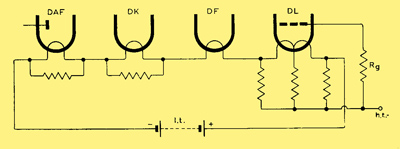
3.2.2.2 Mains operationWhen valves are operated in series from the mains supply via a dropping resistor, the voltage drop across each 1.4 V filament section should have a nominal value of 1.3 V. At 1.3 V the filament current of the 25 mA range is 24 mA and of the 50 mA range is 48 mA. The filament current in the chain should be within ±2% of these values. The voltage drop across the series resistor should be at least six times the sum of the filament voltages in order to minimise the effect of variation in the resistance of individual filaments. The series resistor should preferably be adjusted in each receiver to the required nominal value. It must have a positive temperature coefficient and should be designed to reach a stable temperature shortly after switching on. If these recommendations are followed the equipment can be operated from a mains supply that has normally-encountered voltage variations of up to ±10%. If the equipment is to be used on mains only, and not on dry cells, shunt resistors can be used throughout, instead of the by-pass resistors shown in the recommended circuit. In order to calculate the value of shunt resistor required, the division of cathode current between the two filament limbs must again be known.
4. CapacitancesUnless otherwise stated, the capacitances quoted are measured at 1 MHz with the valve cold in a fully screened socket, with or without an external shield, as stated on the individual data sheets. In practice, allowance should be made for the increase in capacitances due to space-charge effects in the valve, the capacitance of the valve holder itself, and the wiring. An explanation of symbols for capacitances is given in Appendix II.
5. Valve Electrodes
5.1 GeneralValves should always be operated with a DC connection between each electrode and the cathode. It should be noted that the secondary-emission characteristics of valve electrodes may vary from valve to valve, and the use of these characteristics is not in general recommended, except in the case of valves designed as secondary-emission valves.
5.2 Cathode
5.2.1 Voltage between cathode and heaterThe maximum values of cathode-to-heater voltage quoted on individual data sheets are the maximum DC values (unless otherwise stated) and apply to that side of the heater where the cathode-to-heater voltage is greater. Where AC or AC and DC exist between heater and cathode, the DC component must not exceed the published value, and in addition the maximum instantaneous value occurring must never exceed twice the published value, or 300 V whichever is the lesser, unless a specific rating is quoted. This applies to pulse voltages as well as sine-wave voltages. The cathode-to-heater voltage should always be kept as low as possible, and it is preferable to have the cathode positive with respect to the heater. Where the cathode-to-heater voltage cannot be kept low, it is helpful, in the interests of reliability, if the DC resistance is kept as high as possible, consistent with the circuit requirements for hum and cathode-to-heater leakage current.
5.2.2 External resistance between cathode and heaterWhen cathode resistors of high value are used, the valve performance may be influenced by leakage between heater and cathode, which may give rise to difficulties when valves are replaced or the leakage between heater and cathode varies during life. A maximum value of 20 kΩ is therefore recommended for the external resistance between cathode and heater. The maximum may however be increased up to 1 MΩ if the DC component of the cathode-to-heater voltage is such that its instantaneous value never drops below three times the RMS value of the heater voltage. The hum voltage produced across the resistance might assume a rather high value under these conditions.
5.2.3 Rectifier cathodesDisintegration of the cathode coating may occur in both indirectly heated and directly heated rectifiers if the total resistance in series with the anode is less than that specified on the data sheet for the particular valve. The value of the resistance depends upon the effective resistance, Rt due to the transformer. 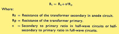
If the resistance Rt is less than the minimum specified value for the limiting resistance, an additional series resistance must be included in the lead to each anode. The wattage rating of this resistor should be at least three times that required for DC only.
5.3 Control gridIn general, it is good practice to keep the resistance of the circuit between the control grid and the cathode as low as possible. It should not exceed the maximum value quoted on the data sheet. Unless otherwise stated the value of Rg1-k max. given in the limiting values refers to operation of the valve with fixed bias. The maximum value for cathode bias operation can be obtained from Fig. 3 (Appendix III). If grid current biasing is employed, the value of grid resistor will depend on the application. For AF voltage amplifiers the grid resistor value should be high (preferably greater than 10 MΩ) but not greater than 22 MΩ. For RF and IF valves the value for normal cathode bias should not be exceeded (i.e. twice the fixed bias value). The values of currents and dissipations should be checked when the grid is connected to cathode. High-slope valves (gm > 5 mA/V) should not generally be operated with grid current bias only unless some DC feedback is included in the form of a screen-grid dropper (in the case of a pentode) or an anode dropper (in the case of a triode), and a low value of cathode resistor (such as that required to compensate for variations in input capacitance with AGC) is incorporated. Compliance with the design-centre limiting values must then be checked with the grid connected directly to the negative end of this cathode resistor. When valves are operated under conditions chosen to give low control-grid currents, the grid resistor value may be very high. If this mode of operation is required the advice of the valve manufacturer should be sought. In circuits where positive control-grid current flows, either continuously or intermittently, the limiting values relevant to the control grid must never be exceeded. Where large signals are applied to the grid of a valve, a grid resistor should be used so that the bias is obtained by grid current rectification, and the variations in the drive will not noticeably affect the valve operating conditions. When this is done, it should be ascertained that limiting values will not be exceeded in the event of loss of drive. This risk may be avoided by providing sufficient cathode bias. If fixed bias is used for a valve, provision should be made for adjusting the bias so that the nominal value of anode current flows. This is particularly important in the case of class "B" output valves when separate adjustment should be provided for each valve.
5.4 Screen gridThe rating chart in Fig. 2 can be used to relate screen-grid dissipation to screen-grid voltage, provided that other limiting values are not exceeded, and that a resistor is used in the screen-grid circuit. For large signal applications, in which the operating conditions of the valve can be varied (for example, by varying the drive) the screen-grid dissipation must be checked at the worst long period running conditions and also during the warm-up period. With speech and music the average level is low compared with the peaks, and operation will be quite satisfactory if the screen-grid dissipation is checked at points up to one third of the output power. In general, the effect of the cathode resistor is reduced by large signals, and a screen-grid resistor becomes necessary. This resistor normally need not drop more than 20% of the HT line voltage. If this resistor is un-bypassed, it need only drop about 10% of the HT line voltage. When a valve with a screen grid is connected as a triode, and specific recommendations are not given in the data, the dissipations of the anode and screen grid should not exceed their individual maximum ratings.
5.5 Suppressor gridThe suppressor grid should normally be connected directly to the cathode or to the negative end of the cathode resistor whichever is more convenient. The suppressor grid should not be used as a control grid unless specific recommendations are made in the data. Where the suppressor grid is so used, care should be taken not to exceed the maximum screen-grid dissipation. When a valve is connected as a triode, the suppressor grid should be connected directly to the cathode, except where other recommendations are given in the data. In applications where the suppressor grid is liable to be driven positive, the value of Rg3-k should not exceed 50 kΩ unless otherwise stated.
5.6 AnodeThe rating chart given in Fig. 2 can be used to relate anode dissipation to anode voltage, providing that other limiting values are not exceeded, and that the load used in the anode circuit is a resistor. For large signal applications, the anode dissipation must be checked at the worst long period running condition. When a triode is used in large signal applications, some resistance should be included in series with its anode. The value required is very dependent on the application, and in the extreme when a triode is biased beyond cut-off and driven well into the positive grid region, e.g. as in class "C" operation, the load impedance in the anode circuit may be sufficient. In this application, however, the use of a cathode resistor is generally recommended to safeguard the valve in the event of loss of drive. If class "B" operation is to be used without a cathode resistor, it must be remembered that large variations can occur near the cut-off point. It is therefore necessary to ensure that all valves will operate at about the same condition, e.g. adjust the bias of each valve to give the required no-signal anode current.
6. Mechanical Considerations
6.1 Mounting positionUnless otherwise stated in the published data, valves can be mounted in any position.
6.2 Valve holdersDetailed drawings of pin spacing, diameter and length are given in BS4482 1953 "Electronic-valve Bases, Caps and Holders". When wiring a valve holder for an all-glass based valve, a wiring jig should be inserted to prevent the contacts being displaced. Such displacement could cause damage to the pins when a valve is inserted in the holder. Dimensions for suitable jigs are given in BS448. Pins marked IC on the base diagram in the data sheet may have been used for connections within the valve. The corresponding contacts on the valve holder must be left free and not be used as anchoring points when wiring.
6.3 Valves with flexible leadsValves with flexible leads do not normally employ plug-in valve holders and it is usually necessary to secure them in position solely by means of the envelope. Any such support should not cause undue stress to be placed on the flexible leads. Attention should also be given to the effect this mounting may have upon bulb temperature. Direct soldered connections to the leads must be at least 5 mm from the seal and any bending of the leads must be at least 1.5 mm from the seal. Precautions should be taken during soldering to ensure that the glass temperature at the seal is not allowed to rise excessively. One simple method is to clamp a thermal shunt to the wire between the glass and the point being soldered.
6.4 DimensionsOnly the dimensions given on the data sheets should be used in the design of equipment. Dimensions taken from individual valves must never be used for this purpose.
7. CoolingAs stated in Section 2.6 the bulb and/or base temperatures must not exceed the published maxima, and it is in general good practice to take steps to ensure that the bulb and base temperatures are kept low. Use may be made of all three methods of cooling, namely convection, radiation and conduction.
7.1 Convection and radiation coolingA valve mounted in free air is cooled by convection currents and by radiation to its surroundings. ln order to make these methods most efficient it is necessary to ensure as free a circulation of air round the valve as possible and to maintain neighbouring bodies at as low a temperature as possible. The design of valve screening or retaining devices should conform to the above principles; that is to say, the device should permit free circulation of cooling air and should reflect as little heat as possible back to the bulb. Where adequate convection cooling cannot be realised because of mechanical limitations, high altitude, or high temperature of the air available for circulation, forced-air cooling or conduction cooling must be adopted.
7.2 Conduction coolingConduction cooling is obtained by mounting the valve in contact with a mass of material which has good heat-conducting properties. This material then acts as a "heat sink". The clamp or can which is used to couple the valve to the heat sink should ensure good thermal contact with the bulb and base of the valve, and should also ensure that the maximum base temperature of165 °C is never exceeded. Heat-sink cooling is particularly suitable for use with flexible-lead valves, as the mechanical arrangements are not likely to allow "free air" cooling, although it should be remembered that the base temperature may be higher than with plug-in valves.
8. MicrophonyWhenever a valve is subjected to vibration, some disturbance in the output of the valve occurs. The effect of this disturbance will depend on the individual application. The published data often make reference to the microphonic sensitivity of different valve types, and this should be noted when a valve type is chosen for a specific application. Where the effects of microphony are found to be objectionable, special steps may have to be taken to reduce the vibration reaching the valve. The chassis itself may show wide variations in amplitude of vibration over its area, due to resonances; therefore favourable location of the valve, or local strengthening of the chassis, may appreciably reduce microphony. A further reduction may be obtained by the use of anti-vibration mountings, but these are likely to be completely ineffective if the vibrations reaching the valve are being transmitted through the air and not through the chassis.
9. HumIf an AC supply is used for valve heaters, the cathode current may be modulated by capacitance and leakage effects between the heater and other electrodes, or by the magnetic field of the heater. This modulation can give rise to hum. The most important electrodes in this respect are the cathode and the control grid. The published limiting value of Vh-k does not give any information about the resulting hum level, but is the maximum permissible voltage below which there is reasonably little danger of breakdown occurring between cathode and heater. The greater the AC component between heater and cathode (or control grid), the greater will be the hum. With AF valves the hum frequency will appear in the audio output; with IF and RF valves it will appear as modulation hum. Hum can also be caused if the leakage resistance between cathode and heater is included in an AF or RF circuit. If it is included in a tuned circuit, the frequency to which the circuit is tuned may be altered by changes in the physical or electrical properties of the cathode-heater insulation (e.g. by vibration of the heater at the supply frequency), resulting in modulation hum. The presence of leakage currents may become apparent as hum or back-ground noise. lt is particularly important that idle valve-holder contacts in the proximity of the control-grid contact should not be used as anchoring points for wires which are connected to the AC supply, as this practice may introduce hum via the capacitances or leakages between valve-holder contacts. This consideration is of particular importance at high supply frequencies.
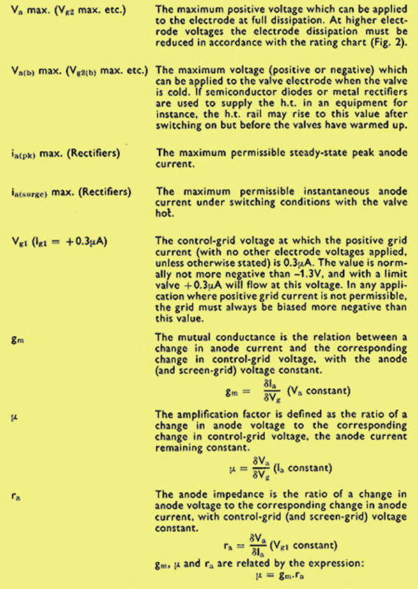
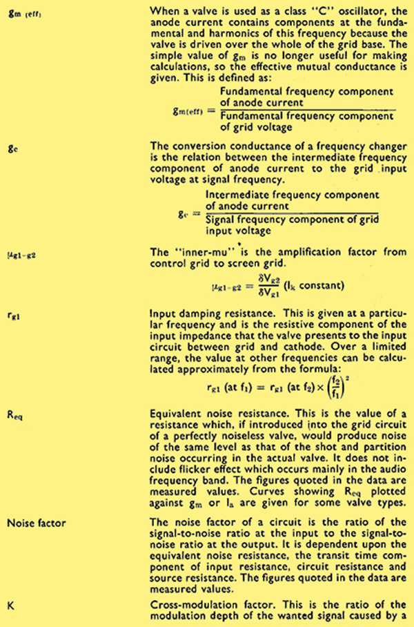
Appendix I - Definitions and Interpretation of Data
The principal characteristics quoted for each receiving valve in the Mullard Handbook are normally those corresponding to the given value of anode current.
The values given are the mean values of measurements made on a large number of valves. All voltages are measured with respect to the cathode, unless otherwise stated.
The following definitions are intended to assist in interpreting the data, as some of these are not sufficiently well known:
Appendix II - Capacitance Symbols
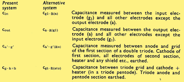
The system of symbols for inter-electrode capacitances in general use at present does not always make it clear where certain of the valve electrodes are connected in making the measurement. For this reason the International Electrotechnical Commission has proposed an alternative system, for use in cases of ambiguity.
In both systems the symbol consists of a letter c followed by subscript letters indicating the valve electrodes between which the capacitance is measured. In addition, the IEC alternative system includes in brackets the valve elements which are connected to reference earth. In order to shorten the symbols in this system, the following two abbreviations are used:
Examples
Appendix III - Rating Charts
Bulb Temperature Rating Chart
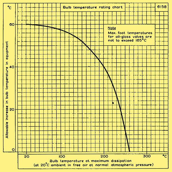
Fig. 1
The above chart shows the increase in bulb temperature that may be allowed, plotted against the bulb temperature attained by the valve when operated at full dissipation in free air at an ambient temperature of 20 °C and normal atmospheric pressure.
To use the chart a measurement must first be made of the bulb temperature at the hottest point of the bulb under the conditions specified above. The hottest point of the bulb is normally opposite the centre of the anode, on the minor axis. The chart can then be used to read off the permissible increase in bulb temperature, and hence establish a maximum bulb temperature for the valve type concerned.
For example, a power valve operated at full dissipation may be found to have a bulb temperature of 220 °C. Reference to the chart shows the allowable increase in bulb temperature to be 32 °C. The maximum bulb temperature for this type is therefore 252 °C. A valve which has very little dissipation may have a bulb temperature of 120 °C. The chart shows that in this case the bulb temperature may be allowed to rise (due to increased ambient) by 56 °C, giving a final bulb temperature of 176 °C.
This curve allows approximately 60 °C increase in ambient temperature for valves having bulb temperatures up to 200 °C (or 165 °C in the case of sub-miniature valves).
The designer should ensure that the maximum bulb temperature rating given by the above chart is not exceeded in his equipment under normal operating conditions.
The maximum foot temperature of all-glass valves must not exceed 165 °C, measured on the glass adjacent to the hottest pin. This is generally the anode pin in the case of high dissipation valves, or the heater pins in the case of low dissipation valves.
Electrode Dissipation Plotted Against Electrode Voltage
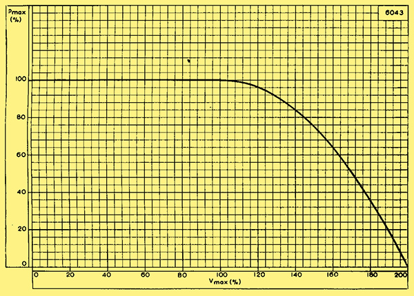
Fig. 2
The above chart shows the relation between the maximum positive electrode voltage and electrode dissipation. At voltages up to the maximum quoted in the data sheet, the maximum electrode dissipation can be used. At voltages in excess of this, the dissipation must be reduced in accordance with the above chart. This permits a supply voltage of twice the maximum permissible electrode voltage to be used, provided that a resistance is included in the circuit.
In cases where a value of Va(b) max. or Vg2(b) max. is given which is less than twice the Va max. or Vg2 max. for the valve, the supply voltage must not exceed this value.
Maximum Value of Grid-to-Cathode Resistor
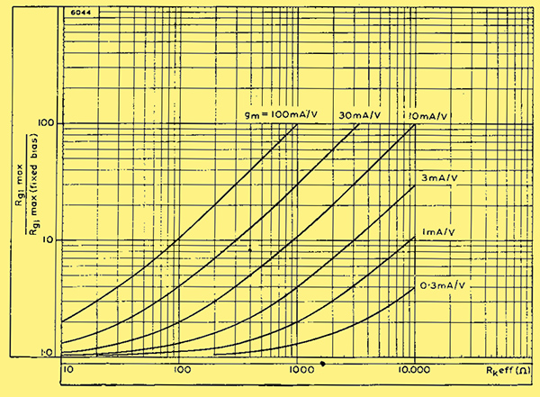
Fig. 3
To find the maximum value of grid-to-cathode resistor which can be used in a given circuit, the mutual conductance of the valve in circuit and the effective cathode resistor must be known. The mutual conductance of the valve in circuit can be determined by measurement.
The effective cathode resistor for a triode is given approximately by:
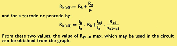
Example
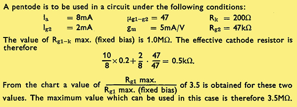
|