|
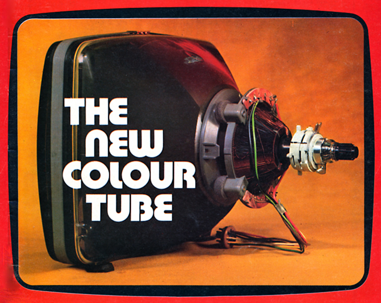
The new colour picture tube introduced in the UK by Thorn and developed in the US by RCA has an abundance of novel features designed to make it easier to operate and perhaps cheaper to produce. It arrives in an aura of snappy abbreviations such as PST ('precision static toroid') and ITC ('integral tube components') but the proud inventors for some reason insist on giving its full name, Precision In-Line System, the full treatment on each appearance. It seems inevitable that others will have no such inhibitions, so we shall draw comparisons between the new PI tube, the standard shadow-mask tube and the Sony Trinitron. These are the only colour display devices in or near large scale production at present.
Over twenty years have passed since RCA introduced the shadow-mask cathode-ray tube, the first colour television display device to be mass produced. For most of this time it has remained the only colour picture tube available and it is now produced under licence to the inventors by many manufacturers all over the world. Detail improvements have been made of course but the basic scheme has remained unchanged: three electron guns in a triangular (or delta) formation, a shadow-mask etched with a pattern of tiny holes and a corresponding array of red, green and blue phosphor dots on the screen.
In the last few years the Sony Trinitron has appeared and soon established itself as a display device for use in the small screen portable receivers for which it was designed. The three -electron guns in this tube are closely spaced side by side in a horizontal plane. The shadow-mask contains vertical slits instead of holes and the screen is composed of vertical phosphor stripes in a red-green-blue sequence.
Need for Dynamic Convergence
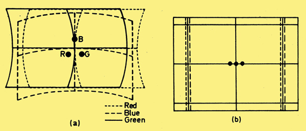
Fig. 1: (a) Basic misconvergence pattern of a delta gun shadow-mask tube. (b) Basic Sony Trinitron convergence errors.
Both these tubes require dynamic convergence correction because although the three beams can be easily adjusted to meet at a common point at the centre of the screen they no longer converge when deflected. The type of misconvergence pattern produced in a delta gun tube is shown in Fig. 1(a) while that produced by the Trinitron is shown in Fig. 1(b). The errors in the first case can be seen to be a complex mixture of horizontal and vertical shifts. The Trinitron misconvergence occurs only in the horizontal direction: also the errors are in practice smaller because the electron beams are closer together. For both these reasons convergence correction is a much simpler process in the Trinitron. Further advantages of the Trinitron are increased brightness and the elimination of moiré interference patterns due to the dot structure of the delta gun phosphor screen.
It was not to be expected that RCA would rest on their twenty year old laurels and they have now introduced their own colour picture tube aimed at the portable (ie smaller screen) receiver market. In some ways it resembles the Trinitron but one very important difference is that it is designed so that no dynamic convergence adjustment is needed.
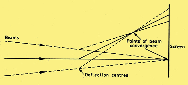
Fig, 2: Three in-line electron beams, viewed from above, when deflected by a uniform magnetic field.
Like the Trinitron, the new tube uses three 'in-line' electron guns mounted in a horizontal plane. This immediately confines convergence problems to horizontal shift. The effect of deflecting the three beams horizontally by a uniform magnetic field can be seen in Fig. 2. The deflected beams converge at a common point before the screen is reached and are diverging therefore at the screen.
Effect of Astigmatic Field
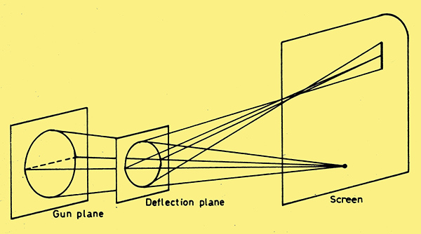
Fig. 3: A circular beam deflected by an astigmatic field is brought to a line focus at the screen.
The designer of the deflection coils for a picture tube has as one of his aims the elimination of deflection defocusing of the electron beam, i.e. the tendency of the beam to become progressively defocused as the deflection angle increases. In a colour tube this effect produces 'over-convergence'. It is possible however by adjusting the position of the turns of the coil round its former to produce an astigmatic field so that the deflected beam is always focused to a vertical line instead of a spot. This is illustrated in Fig. 3. In this diagram the circles represent the diameter of a 'fat' beam of electrons reducing in diameter as it is brought to a focus at the screen.
The designer of the deflection coils for a picture tube has as one of his aims the elimination of deflection defocusing of the electron beam, i.e. the tendency of the beam to become progressively defocused as the deflection angle increases. In a colour tube this effect produces 'over-convergence'. It is possible however by adjusting the position of the turns of the coil round its former to produce an astigmatic field so that the deflected beam is always focused to a vertical line instead of a spot. This is illustrated in Fig. 3. In this diagram the circles represent the diameter of a 'fat' beam of electrons reducing in diameter as it is brought to a focus at the screen.
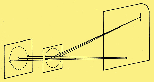
Fig. 4: Three beams on the horizontal axis of the fat beam shown in Fig. 3 are always converged by the astigmatic deflection field.
Now the three guns of the PI tube can be imagined to lie on the horizontal diameter of the gun plane circle as shown in Fig. 4. Following the paths of the electrons from the same points indicated in Fig. 3 it is found that the electrons all converge to the centre of the vertical line of focus at the screen. So in this particular case the astigmatic field has the effect of automatically converging the three in-line beams to a common point - instead of the line focus that would be obtained with one large diameter beam. This is the principle on which the PI tube relies to achieve self convergence. Trying to make the principle work with conventional techniques of manufacturing and mounting scan coils and electron guns would be difficult if not impossible. To produce a field which gives exactly the right correction implies very precise alignment of the non- uniform scanning field with the electron beams and precise construction of the scan coil assembly. The word 'precision' in the name of this new tube is not a product of the marketing manbs imagination: it is an engineering necessity.
PST Yoke
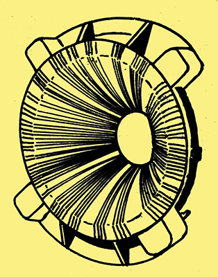
Fig. 5: The precision static toroid deflection yoke which produces the required astigmatic deflection field.
The scan coil assembly used is shown in Fig. 5 and is called a 'precision static toroid' (PST). The position of each turn is defined by placing it in slots in moulded plastic rings which are cemented to each end of the core, the distribution of turns around the core being designed to give the required non-uniform horizontal deflection field. It has been found that this form of construction gives extremely consistent results. Typical PST figures for Thorn 16/18in. tubes are: line coil inductance 0.158 mH (parallel). or 0.632 mH (series connected); for the series connected field coils the resistance is 2.2Ω).
Effect of Misalignment
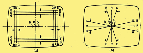
Fig. 6: (a) Convergence effect (shown by arrows) as the yoke is moved horizontally to the left from a misplaced position to the right. (b) Convergence effect as the yoke is moved verticaIIy upwards.
If the deflecting field strength applied to each beam is different the position of the scan coil assembly must be critical since movement of this in the plane perpendicular to the axis of the tube will alter the field strength at the deflection centre of each beam. The effect of such a movement is shown in Fig. 6. In (a) the scan coil has been moved to the right of its correct position (as seen by the viewer). The blue beam is now passing through a stronger field so the blue raster is expanded relative to red. The green raster is correspondingly reduced in size. Clearly the lateral position of the scan coil must be adjusted to equalise the size of the three rasters. If the scan coil is moved vertically the effect is to rotate the blue and green rasters relative to red as shown for example in Fig. 6(b). Again, very careful adjustment of the position of the scan coil assembly is seen to be necessary so that the field is symmetrical about the axis of the three beams. The sensitivity of these adjustments is such that the visible change in convergence is about equal to the scan coil movement
At this point it may seem that the designers have only eliminated one tedious adjustment (dynamic convergence) by replacing it with another (critical lateral and vertical shift of the scan coils). The basic idea of the PI tube however is that the scan coil assembly is treated as part of the tube assembly. It is fixed in its optimum position on the tube at the factory and no further adjustment is required or possible. The scan coil may be separated from the tube only by heating it sufficiently to soften the thermoplastic cement which normally locks it in position. If a tube is replaced the PST will be automatically replaced with it.
In-Line Electron Guns
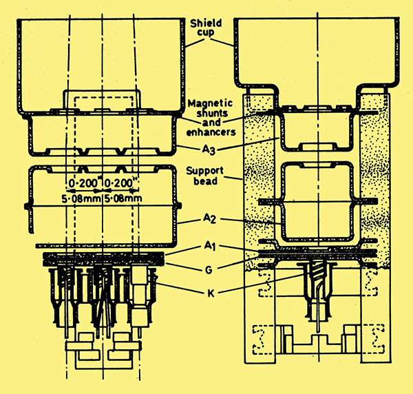
Fig. 7: Cross-section of the precision in-line gun assembly.
The spacing of the three beams must also be defined with precision. The design figure is only 0.200 in. and this helps to minimise any tendency of the three beams to mis-converge. The beams must also lie in an exactly horizontal plane if the self convergence is to be effective. These requirements are met by forming the three 'grids' from a single piece of flat (or planar) metal punched with three accurately located holes which determine the relative position of the three beams at this point with a tolerance of less than 0.25%. This grid electrode can be seen in the cross-section drawing in Fig. 7. In circuit terms of course this means that the three grids are at a common potential so that the tube cannot be used with grid drive or colour-difference drive.
The remaining electrodes accelerate and focus the electrons, the beams initially following parallel paths. The separation of the apertures in the A3 electrode is slightly increased however: this has the effect of bending the outer beams towards the axis, thus providing most of the static convergence. Fine adjustment is provided by a magnetic field system which is described later. The angular deflection needed for this is less than one degree.
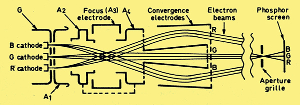
Fig. 8: Electron beam trajectories in the 13 in. Sonny Trinitron tube.
Fig. 7 shows that the beams remain in parallel paths as they pass through the focus field. This makes an interesting comparison with the Trinitron. In the latter tube the in-line beams cross over at the centre of the focus field (see Fig. 8) so that each beam passes through the centre of a relatively large diameter electrode system. This is claimed to reduce aberrations that would otherwise spoil the focus of the outer beams. Since there is only one focus electrode system for all three beams this 'large diameter' gun fits into a tube neck whose diameter is 29 mm - the familiar 90° delta gun tube has a neck diameter of 36.5 mm. As it happens the neck diameter of the new PI tube turns out to be the same as that of the Trinitron, 29 mm. The smaller the neck diameter the less the scan power required for a given angular deflection.
Magnetic Shunts and Enhancers
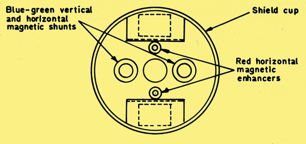
Fig. 9: Front view of the precision in-line electron gun, showing the positions of the magnetic shunts and enhancers.
One other novel feature of the electron gun design should be mentioned. Four magnetic rings are mounted. on the A3 electrode as shown in Figs. 7 and 9. These act in rather the same way as a partial magnetic screen. Some of the deflection field is diverted through the material of the rings, reducing the field strength within the ring and modifying the field pattern in the vicinity of the ring.
The effect on the rasters is that the blue and green magnetic shunts reduce the size of the rasters produced by these beams while the red magnetic enhancers increase the width only of the red raster. All this is designed to ensure that the centre beam lands between the outer beams at all points on the screen. The makers claim that in a colour tube convergence errors of the red beam are the most noticeable (agreed?) and for this reason they have associated the centre beam with the red phosphor. This again invites comparison with the Trinitron whose centre beam is directed to the green phosphor because it has the best focus and the green primary signal makes the greatest contribution to the high-definition luminance component of the picture.
shadow-mask
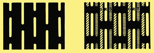
Fig. 10 (left): Arrangement of the slit-shaped apertures in the mask. Fig. 11 (right): Impression of what is seen close up on the tube screen when the phosphor stripes are energised by the electron beams.
The horizontal in-line arrangement of the electron guns in the PI tube means that as in the Trinitron the apertures in the shadow-mask could be vertical slits associated with vertical phosphor stripes on the screen. If this is done however the mask can be curved in only the horizontal direction. The designers of the PI tube wanted to follow delta gun tube practice, using a mask with spherical curvature matching that of a similarly curved screen. The necessary mechanical rigidity to make this possible is obtained by using a compromise between holes and full-length vertical slits as shown in Fig. 10: this shows - much enlarged of course - the vertically elongated holes in the mask. The horizontal cross-ties allow the mask to be given slight spherical curvature. The all important 'transparency' of the mask can be estimated from this diagram (that is the proportion of the mask area through which electrons can pass and reach the screen so as to contribute to the picture brightness). It appears to be about 16%, a similar figure to that for modern delta gun tubes and rather less than the 20% claimed for the Trinitron.
Screen
As phosphor stripes are used the whole screen can be covered with phosphor with no wasted areas as there are between the phosphor dots on a conventional shadow-mask tube. It is not possible to energise the whole of this area however because of the cross-ties in the mask and because to ensure good colour purity it is necessary to make the image of the slit slightly less than the width of the phosphor stripe. An idea of the appearance of the screen close up in a 'white' area of the picture is shown in Fig. 11: each slit in the mask is reproduced on the screen in the three primary colours as the three beams pass through it from different directions to land on their respective phosphor stripes.
Each stripe is 0.0108 in wide, so any one colour stripe is repeated at 0.0324 in. pitch. Even on the smallest (16 in.) diagonal tube this permits almost the full horizontal resolution to be displayed, with corresponding improvement in the 18 and 20 in. tubes which use the same stripe spacing and therefore have more stripes across the width of the picture. A striped screen structure sets no limit to the vertical resolution of course.
Static Convergence and Colour Purity Adjustment
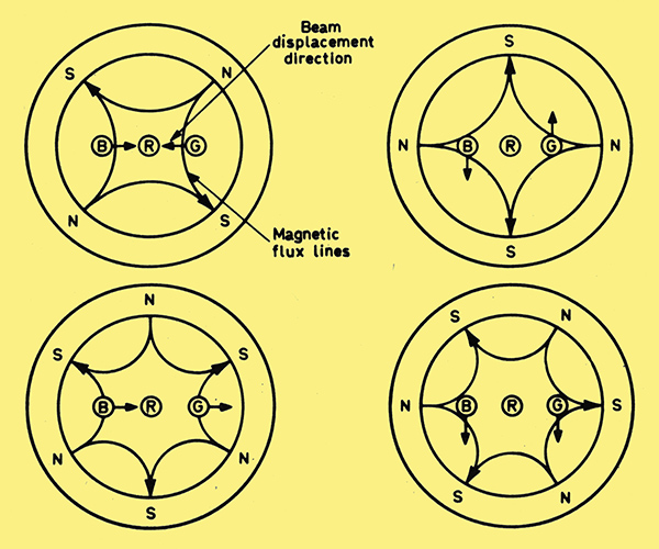
Fig. 12 (above): A four-pole field moves the outer (blue and green) beams in opposite directions. Fig, 13 (below): A six-pole fieId moves the outer beams in the same direction.
Even now the list of novel features of the PI tube is not quite exhausted. The arrangements for adjusting colour purity are conventional although only a horizontal shift is required. But the static convergence adjustment is provided by an ingenious magnetic field pattern provided by permanent magnets requiring no internal pole pieces. The magnets are mounted in four plastic rings. In one pair of these rings the magnets are arranged to provide a four-pole field as shown in Fig. 12. The field is zero at the centre of the ring so the centre (red) beam is not affected. The blue and green beams are shifted in opposite directions and the magnitude and direction of this shift is controlled by rotating the rings in the same way as is done for colour purity adjustment with a delta gun tube. That is, rotation of the rings in the same direction varies the direction of shift while turning the rings in opposite directions varies the amount of the shift.
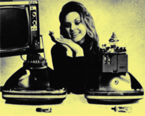
Fig. 14: Comparison of the new tube with its integral deflection yoke on the left and on the right a conventional delta gun shadow-mask tube. Note that it is common US practice to mount the convergence controls on the deflection/convergence assembly with standard delta gun shadow-mask tubes.
In the second pair of rings each ring provides a six-pole field as shown in Fig. 13. Again the centre beam is unaffected while the outer beams are now moved in the same direction. The two rings of each pair make it possible to vary the amount and direction of shift. Adjustment of static convergence requires the rotation of four magnetic rings therefore. The rings can be easily identified in the photograph of the PI tube shown alongside its more venerable relative in Fig. 14. They are spaced well away from the PST and are made of barium ferrite which has a permeability of about one. The deflection field is not distorted therefore by the presence of the convergence magnets.
Tube Sizes
The PI tube is not regarded by its designers as a replacement for the delta gun shadow-mask tube for picture sizes above 20 in but rather as a strong competitor for use in the portable receiver market. The initial plans are to produce it in 16, 18 and 20 in sizes. The 20 in. PI tube is about two inches shorter than the 90° delta gun tube. This difference can be clearly seen in Fig. 14 which also shows that the in-line electron gun assembly (in front of the tube) is significantly shorter than that used in the delta gun design. The 16 in PI tube has an overall length of 14.2 in which makes an interesting comparison with the twelve inch Trinitron tube whose overall length is slightly greater at 14.4 in. For a tube intended for use in portable receivers it is also note-worthy that the new Thorn/RCA tube in the 20 in size is nearly three pounds lighter than its delta gun counterpart (with the scanning and convergence components included in the comparison).
|