|
An interesting description of some novel 'tetrode [*] At the end of the 1920s the bi-grid was called the Tetrode and the tetrode was known as the Screen-Grid valve. This article makes use of the term tetrode throughout. -Ed.' rectifying circuits with which extremely good results can be obtained. A special feature of these circuits is that they operate on very low HT voltages.
There is something about the valve detector that always appeals to me; both in theory and practice I find it quite the most fascinating stage of the receiver. Perhaps this is because it functions so differently from the valve amplifier, It is not so simple in theory, nor so perfect in practice, yet amazing results are often obtained with a simple one-valve detector set.
The unique position of the detector valve as transformer of HF into LF energy whereby the inaudible incoming HF currents are made audible, gives rise to intriguing complications which are of great interest when designing a receiver for the highest efficiency and freedom from distortion. We have yet to develop the valve detector which shall transform HF into LF energy with a hundred percent efficiency and without distortion.
Improved Valves
Now after all, this I must not encourage you to believe that I am going to describe some new detector arrangements approaching this ideal. The subject of this article has to do with the development of the double-grid or tetrode valve as a detector, and I hope to show that as a rectifier it does certainly give better results than the ordinary valve. Some years ago the tetrode valve was first put to practical use for broadcast sets by Messrs. Dowding and Rogers in the Unidyne circuit, of which they were the originators. This detector circuit gave excellent results without any HT battery at all, but owing to the deficiencies of available tetrode valves then the tetrode detector has never been widely used.
Now, however, owing to the enterprise of a firm of British manufacturers, Messrs. Aneloy Products, we have available some very efficient tetrodes of various types - HF, RC, power, super-power, etc., This of course, lends quite a new interest to the study of the tetrode valve. Although I find the ordinary valve as a detector of great interest, the tetrode in the same capacity has proved even more attractive. An account of some of my experiments may therefore be of interest to other amateurs who wish to keep abreast of new developments.
Use of Inner Grid
Before launching out upon experiments with the tetrode either as amplifier or detector, it is necessary to become familiar with one or two fundamental points about this type of valve.
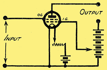
Fig. 1.
First of all, you will observe from Fig. 1, that, of the two grids, the one nearer the filament is given a small positive potential by connecting it to a suitable tapping point on the HT battery.
The other (outer) grid is used as the control electrode like the single grid of the ordinary valve. Now the effect of making the inner grid positive is to reduce very considerably the anode-filament resistance of the valve so that for a given positive anode voltage a greater anode current flows through the valve than if the positive inner grid were not there.
The tetrode, therefore, is able to do the work of an ordinary valve with a considerably smaller HT voltage. This reduction in the working anode voltage is the primary feature of the tetrode, and some of the modern types require but one-third to half the anode voltage of the three-electrode valve for the same results.
Variable Factors
The second fundamental feature of the tetrode is that the degree of amplification obtainable, or in other words, the magnification factor of the valve, depends upon whether the inner or the outer grid is made the positive electrode. If the latter is so used then a marked increase in the magnification factor is noticed, and although the impedance of the valve is also increased yet it is considerably lower than the impedance of the three electrode valve having the same magnification factor.
Because of its lower impedance the RC type of tetrode gives as much amplification on 60 Volts HT as an ordinary valve of the same type gives on 120 Volts HT In detector circuits it is therefore usual to connect the outer grid to the HT battery in order to obtain the benefit of high amplification on a relatively low anode voltage.
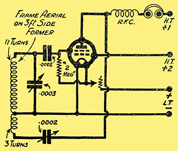
Fig. 2.
Returning to practical considerations, We have in Fig. 2 the theoretical circuit of one of the first experimental receivers put on test. This is nothing but the ordinary one-valve set with capacity-controlled reaction, the inner grid producing the necessary reduction in the impedance as described above.
From Fig. 2 you will see that it is an easy. matter to replace the tetrode by an ordinary valve, and this facilitates comparisons between the two types. As it is easier to make comparisons of results on a weak signal I used a 3-ft. frame aerial instead of the normal outdoor wire.
Smoother Reaction
I then found that while an efficient type of three electrode valve required 30 Volts HT for good phone signals at 15 miles from 2LO, the tetrode yielded equivalent results with so low an anode voltage as 9 Volts with 6 Volts on the inner grid. Moreover, with the tetrode the control of reaction was very much smoother, requiring no delicate adjustments of grid and anode -potentials as with the ordinary valve. The remarkably smooth control of reaction is quite a feature of the tetrode detector and this makes it doubly attractive for Short-Wave work where absolute freedom from 'backlash' in the reaction control is really essential for good reception.
The practical result of replacing the ordinary valve detector by a tetrode is to obtain equal rectification efficiency, smoother reaction control, with a considerable reduction in battery power. This was found to hold good for other detector circuit arrangements, and in every case application of the anode voltages normally associated with the three-electrode detector resulted in signals considerably louder than any provided by the latter.
In these circuits where the inner grid is made positive we are using the tetrode solely as a low anode-voltage detector, and the most suitable valves are the general-purpose and low-frequency types. Of the latter the AP412LF is a good example.
Now the high-magnification tetrode, where the outer grid is made positive as described above, is also quite easily substituted for the ordinary valve, requiring only another connection from the outer grid to the HT battery. The best valve for the ordinary regenerative circuit is of the type AP412HF.
Louder Signals
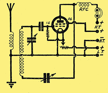
Fig. 3.
The latter valve has the outer grid connected to a terminal on the valve base, whereas in the LF types the inner grid is so connected. A representative circuit using this valve is given in Fig. 3, and an experimental receiver based on this circuit was found to give very good results, signal strength being greater than with circuits such as that of Fig. 2.
An enthusiastic experimenter of my acquaintance, living on the outskirts of London, receives quite clearly such distant stations as Aberdeen, Berlin, and other Continentals, etc., on an indoor aerial and the circuit of Fig. 3, using nothing more than a 9 Volt grid-bias battery as HT supply!
This type of tetrode detector is certainly admirably suited to DX work on the minimum of power, and there is nothing to equal the thrill of logging some distant station on such la small set as a single detector valve. With this circuit reaction control was also noticeably smooth and even.
High Magnification Valves
The high-magnification tetrode detector, like the corresponding RC. type three-electrode valve, is peculiarly suited to resistance-capacity coupling. Very often an RC valve is used in the detector stage, usually when preceded by an HF valve, anode-bend rectification being employed. In such cases a tetrode of the type AP412HF, or 412RC can be substituted, with the advantage of retaining the same degree of amplification while using not more than 60 Volts HT.
When a resistance-coupled detector is not preceded by an HF stage, it is often difficult to obtain a sufficient degree of reaction. The special circuits described below are more satisfactory in this respect.
Several interesting things happen when the tetrode is used in special detector circuits which are only possible with the four-electrode construction where we have another grid to play with. These circuits introduce several new features of interest.
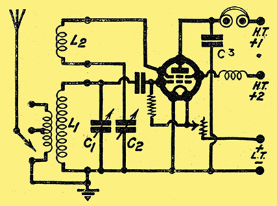
Fig. 4.
One of these special circuits is reproduced in Fig. 4, and this forms the basis of a successful experimental one-valver used by the author. The receiver is really just the ordinary regenerative detector-valve high-magnification type, but with the essential difference that the outer grid is used as the reaction 'anode', the actual anode being reserved for the audio-frequency output only. This results in an exceedingly smooth reaction control without critical adjustments, while other advantages accrue from the separation of the LF and HF output at the anode itself.
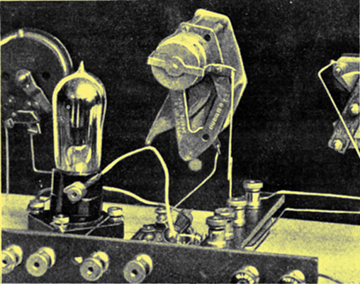
This photo very clearly shows the connection to the inner grid of a typical four-electrode valve. The lead provided with a spade terminal takes this inner grid direct to an HT plus terminal in accordance with the circuit illustrated in Fig. 1.
The photograph above is a close-up of the tetrode valve, showing, the method of making connection to the outer grid terminal on the valve-cap by means of a flexible lead terminating in a spade terminal, the valve used being an AP412HF.
This experimental one-valve set was first of all used without any aerial or earth, in order to study the best adjustments for rectification efficiency and reaction control.
Less Filament Current
The first thing to be noticed was that no reaction effects could be obtained until the outer-grid potential reached some 12 Volts positive. Below this the set would not regenerate, however much it was coaxed. Also, if the anode potential was more than 20 Volts or so, the outer-grid potential needed a slight increase for maximum reaction, every increase in one requiring an increase in the other. There appeared to be no definite ratio between anode and outer-grid volts for the best results.
As regards the filament voltage, although the AP412HF valve is rated at 3.8 to 4 Volts, it was never found necessary with these low battery voltages to attain this figure; 3 Volts being ample. The normal filament current is only required when much higher anode and outer-grid voltages are used. There is, therefore, some economy in filament current.
The adjustment of grid potential for efficient rectification proceeds in the normal manner as for ordinary valves, the grid-condenser method of rectification, as in the case of the latter, giving the louder signals. For anode-bend rectification a grid bias of 4.5 to 6 volts negative was found necessary.
The receiver was next connected to the frame aerial mentioned above, and very good phone signals were obtained from 2LO at fifteen miles, and from 5GB, the latter being nearly as strong as the London station. Quite a number of foreign stations were received fairly well after dark, and for weak signals quite low voltages were found necessary, just enough on the outer grid to produce sufficient reaction for easy control.
Excellent DX
When connected to a normal outside aerial over a dozen foreign stations were received in broad daylight, signals being very clear. On the whole the signal strength obtained was exceptionally good in view of the small battery voltages used. For similar results the best three-electrode valve requires at least treble these voltages.
One curious effect noticed was the necessity of connecting, a small fixed condenser, about -0.0001 to 0.0002 μF, from anode to filament negative. Without this condenser the capacity of the reaction condenser had to be increased to produce sufficient reaction. Similarly, the insertion of an HF choke in the anode lead increased the difficulty of obtaining sufficient reaction. The necessary anode bypass condenser C3 is shown in Fig. 4.
In my opinion the most important feature of this detector arrangement is that it is eminently suitable for RC coupling. Unlike the usual arrangement no difficulty is experienced in obtaining sufficient reaction.
A Successful Circuit
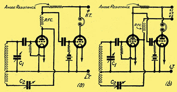
Fig. 5.
Moreover, if you compare Figs. 5a and 5b you will see that there is no condenser in parallel with the anode resistance, of diagram (b). This is an advantage because the condenser C2 of diagram (a) is virtually in parallel with the anode resistance, thus decreasing the amplification on high notes. The circuit of 5b works very well indeed.
In one of the photographs you will see another experimental receiver wherein a transformer-coupled amplifier has been added to the detector. Both valves are tetrodes, the detector being an AP412HF, and the amplifier an AP412P. The addition of an LF amplifier presents no difficulty whatever, and the necessary connections are made in the orthodox way, as will be seen from Fig. 6.
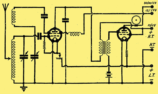
Fig. 6.
Notice that another connection is required to the HT battery for the second grid of the LF amplifier, in this case the inner grid, as is usual for tetrodes when used as amplifiers. The anode of the detector and the inner grid of the amplifier can very well be given a common terminal as the required voltages in each case are about the same.
In its final form this receiver gave excellent loud-speaker results on an outdoor aerial from 2LO and 5GB. Quality was all that could be desired, and volume of signals up to the standard of the normal two-valve set supplied with much higher battery voltages. In the case of the present receiver the maximum anode potential applied to the, amplifier never exceeded 40 Volts, and even with 30 Volts results were extraordinarily good, the second valve handling quite a respectable input without distortion.
The LF Transformer
As l regards the transformer, a component having a ratio of 3 to 1; with a generous primary, was found most suited to this type of tetrode detector. You will notice in the photograph of the receiver that a Short-Wave coil is shown in position. With this tuning unit reception was carried out on the lower band of short wave length with very satisfying results.
A slightly different HF choke was found to be necessary here, and a replaceable type was used, as will be seen from the photograph. While no great amount of time was devoted to Short-Wave reception several interesting transmissions were received, and on one occasion 2FC, the Sydney Short-Wave station, was heard quite clearly. On all occasions the control of reaction provided by this detector-valve arrangement proved eminently satisfactory for Short-Wave reception. For the best results a grid leak of 5 MΩ and rather low outer-grid voltages were found necessary.
As you are doubtless aware, the best Short-Wave set is undoubtedly a simple regenerative detector followed by one stage of LF amplification, the control of reaction being the smoothest obtainable. In all these respects this two-valve set was quite satisfactory, and even with the detector on the verge of oscillation no threshold howl developed, as is very often the case with the three-electrode detector when transformer-coupled.
A Definite Improvement
As a result of these experiments I am led to the conclusion that the tetrode as a detector is certainly an advance on the three-electrode valve. Apart from the reduction in HT battery voltage, the special circuits mentioned above give considerable amplification and remarkably smooth control of reaction.
Although the ability to ruse low anode voltages is not a great advantage where the detector is used in a multi-valve receiver in connection with an HT eliminator, it is of great importance in one-valve sets and small receivers in general, particularly in view of the novelty and efficiency of the reaction control in special circuits.
Also, when worked with higher potentials up to 30 or 40 Volts, the tetrode detector is capable of a greater undistorted LF output than is possible with the three-electrode valve supplied with the same anode voltage.
Therefore I can advise all experimenters to try tetrode valves, especially in their smaller sets and in their Short-Wavers. I am sure they will be agreeably surprised at the results they obtain, and will think twice before they go back to ordinary three-electrode detectors - if, indeed, they ever go back.
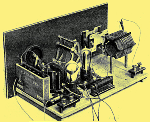
A short-wave receiver using two four-electrode valves. The connections to the additional grids are made to small screw terminals fixed on the bases of the valves. You will notice a flexible lead is joined to the additional terminal on the nearer tetrode.
|