|
Principles of Operation
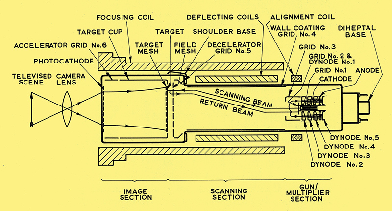
Schematic arrangement of the 4.5 inch image orthicon.
See also New Television Camera Tube
For descriptive purposes, the tube may be divided into three sections, the image section, the scanning section and the multiplier section, as shown above.
Image Section
The image section contains a semi-transparent photo-cathode on the inside of the faceplate, and electrodes to provide an accelerating electrostatic field to the target. The latter consists of a thin glass disc with a fine mesh screen mounted very closely to it on the photo-cathode side.
An image of the scene to be televised is focused by an optical lens system on to the photo-cathode and causes photo-electrons to be emitted. This photo-electron emission is proportional to the intensity of the optical image at any particular point. The photo-electrons are focused on to the target by the combined action of the electrostatic field and a longitudinal magnetic field, the latter being produced by an external coil. The magnetic field is so graded that the image formed at the target covers approximately three times the area of the image at the photo-cathode.
Secondary electrons are produced by the impact of the photo-electrons on the target and these are collected by the fine mesh screen which is held at a definite small positive potential with respect to the target. The screen potential limits the excursion of the target and ensures complete stability at all light levels. The secondary emission at the target produces a pattern of positive charges corresponding point by point with the light distribution of the original scene and the thinness of the target allows this charge pattern to be reproduced immediately on its reverse side, i.e. the scanned side.
Scanning Section
The face of the target remote from the photo-cathode is scanned by an electron beam emanating from a triode electron gun, the potentials being so adjusted that the beam approaches the target with a substantially zero velocity and is, therefore, unable to produce unwanted secondary electrons.
The beam is focused at the target by the magnetic field of the external focusing coil and the electrostatic field of the wall coating (grid No. 4), and deflection is accomplished by transverse magnetic fields produced by external deflection coils. The beam is aligned with the focusing magnetic field by means of a small transverse magnetic field produced by external coils located at the gun end of the focusing coil.
The target end of the wall coating (grid No. 4) is closed by a fine mesh screen called the field correcting mesh. This is maintained at a potential a few volts positive with respect to the wall coating. In addition to improving the landing characteristics of the beam at the target, the presence of the field correcting mesh reduces the intensity of the white edging typical of pictures produced by earlier versions of the image orthicon.
The edge field at the end of the beam focusing electrode is controlled by adjusting the potential of the decelerator (grid No. 5) which is situated between grid No. 4 and the field mesh. This adjustment helps to improve the landing characteristics of the beam.
As a precaution against light leakage, which has been shown to cause spurious results, the gun end of the tube is coated with an opaque enamel.
Multiplier Section
The return beam, comprising electrons which are not required for neutralising the charge on the target, travels back along approximately the same path as the outgoing electron beam and is directed into a five-stage electron multiplier where it is amplified to become the output video signal. In order to reduce the intensity of the image of the first dynode which will be super-imposed on the transmitted picture, the whole of the multiplier section assembly is mounted off centre.
The multiplier gives an overall multiplication from the five stages of between 500 and 2,000. This is sufficiently high to bring the random noise of the electron beam well above that of the input stage of the camera head amplifier and is, therefore, the limiting noise factor in the use of the tube. The multiplier also permits the use of an external amplifier of lower gain.
It will be appreciated that when the beam moves from a less positive portion of the target to a more positive portion, the signal output voltage across the load resistor changes in the positive direction. Hence, for highlights in the scene, the grid of the first video amplifier valve swings in the positive direction.
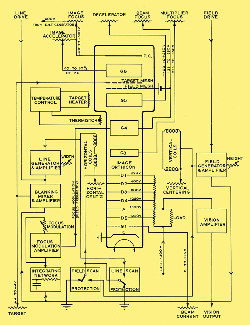
Block diagram of image orthicon and associated control units.
|