|

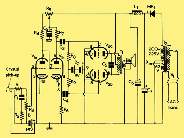
The Circuit of the experimental two valve amplifier.
Our contributor describes a simple audio amplifier which incorporates a number of unusual features, The voltage amplifier and phase-splitter uses an ECC83 and the output stage uses an ECC82 double triode. We present the unit as an experimental project for readers who are interested in somewhat unconventional circuits.
The accompanying circuit diagram illustrates a simple amplifier which employs two inexpensive double-triodes. The prototype has given good results and was designed to operate with a minimum of components. A feature of the circuit is that the low HT consumption enables a 'converter' mains transformer to be employed, with the result that complete isolation from the mains supply is achieved at low cost.
The Circuit
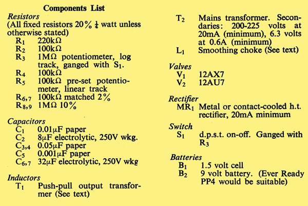
In the circuit diagram, a crystal pick-up connects to the tone correction circuit offered by R1, R2 and C1, and to the volume control R3. The audio tapped off by the slider of this control is then fed to the grid of the voltage amplifier V1(a). The anode of V1(a) couples directly to the grid of the phase-splitter triode, V1(b). Out-of-phase voltages then appear at the anode and cathode of V1(b) and are applied, via C3 and C4, to the grids of the 12AU7, V2. The anodes of V2 finally connect to a push-pull output transformer, T1, capacitor C5 providing a level of top-cut.
The HT supply is obtained from the half-wave secondary of the mains transformer, T2, and is rectified by any suitable rectifier capable of operating at the secondary voltage and at a current of 20mA. The rectified voltage is applied to the reservoir capacitor C7, and is smoothed by L1 and C6. It is possible for the choke to be replaced by a resistor having a value of 2.7kΩ and a rating of 2 Watts, but this was not tried by the author.
It will be noted that bias for V1(a) and V2 is provided by a dry cell and dry battery respectively. This method of biasing was employed as it was felt that the cost was less than would be given with normal cathode bias components and because, in the case of V2, the valve received a higher effective HT voltage. As no current is drawn from the dry cell and battery, their life is equivalent to their shelf life. If desired, however, it would be possible to dispense with the 1.5 Volt cell biasing V1(a) and insert a 2.7kΩ resistor in the cathode lead instead. This could then be bypassed by a 25 μF electrolytic capacitor if it was found that gain was too low or that hum was introduced into the cathode circuit. If the cathode bias resistor is fitted, the lower ends of R2 and R3, and the lower terminal of the pick-up, are returned to chassis.
The 100kΩ preset potentiometer, R5, offers a convenient method of setting V1(b) to its optimum working condition with respect to bias, and is adjusted at various volume levels to obtain the best performance. The output transformer employed in the prototype was a component offering 8kΩ impedance anode-to-anode (i.e. 26+26:1 for a 3Ω speaker), but it is probable that better results would be given by a transformer offering 12 to 14kΩ anode-to-anode impedance. These impedances correspond, for a 3Ω speaker, to a ratio of the order of 33+33:1.

See also A 600 mW Low Power Amplifier.
|