|
Improved high-frequency response.
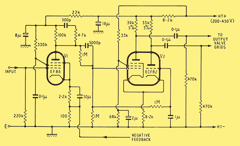
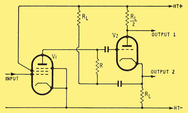
Circuit of complete EF86 pentode amplifier and ECF82 phase-splitter for use in a high-fidelity amplifier with a large amount of negative feedback.
In the past many phase-splitters have been investigated and the reader would be quite justified in asking why a further circuit has been developed. The answer is quite simple in that the performance of high-fidelity amplifiers may be no longer limited by the output-transformer but by the response of the phase-inverter. With the best transformers available this is very true, and the improvement in amplifier performance that is obtained by using better circuits is quite startling.
In order that the reasons for discarding the present circuits may be seen, it is essential that all the requirements of the phase-inverter be first evaluated.
The first requirement of all phase-inverters is that they should deliver an output that is balanced to within a few per cent and does not alter as the valves age in use. Most of the phase-inverter circuits in use have this property, but the paraphase-inverter (below) does not, as there is no negative feedback to stabilize the gain of the stage.
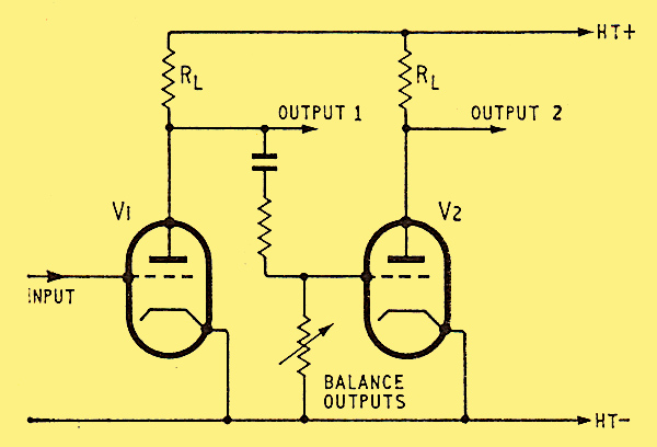
Basic circuit of paraphrase phase-splitter.
The second requirement is that the output-impedances from both halves of the phase-splitter should be approximately equal. The reason for this is nothing like so obvious at first sight. In fact there are two reasons for this requirement. The first is that severe grid-blocking can occur if the amplifier is accidentally over-driven [1] High Fidelity Sound Engineering, N H Crowhurst (Newnes), p. 130.. This can be overcome by using high-value grid stoppers but this gives an additional high-frequency time-constant due to the input capacitance of the following stage. As will be mentioned later, this gives a very undesirable tendency to HF oscillation when high values of negative-feedback are applied. The second disadvantage is that the drive to the two output valves may unbalance severely at high frequencies due to the different time-constants produced. This will have the effect of severely limiting the HF power available and will also increase the HF distortion. The two circuits that suffer from this drawback are the floating paraphase
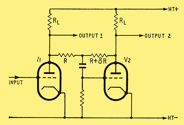
Basic circuit of 'floating' paraphrase phase-splitter.
and the concertina.
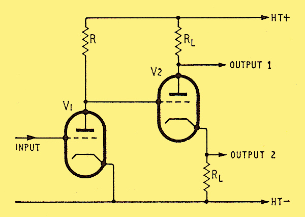
Basic circuit of direct-coupled concertina phase-splitter.
In both circuits the valve loads that drive the output stage are balanced, but unfortunately the output impedances are not balanced. This is due to the voltage negative-feedback inherent in the circuits. This negative-feedback overcomes the problem of valve ageing mentioned before, but brings the disadvantages that have been just mentioned. In addition, these circuits are not readily DC coupled to the previous stage. This is a severe disadvantage where large amounts of feedback are contemplated, as the additional low-frequency time-constant of a further coupling capacitor can easily cause instability at low frequencies.
Up to the present it seems to have been generally assumed that these were the only circuits to be avoided, if at all possible. Unfortunately this has proved not to be the case and the cause of the distressing tendency of high-feedback amplifiers to go unstable can often be laid at the door of the phase-splitter. The reason is quite simply one of poor HF response. A poor HF response in the phase-splitter will cause a falling loop gain, but what is more important it will also give a phase shift that tends towards 90 degrees retard. Now, if there is a total of 180 degrees retard at some high frequency the feedback will no longer be negative but positive. If the gain round the amplifier loop exceeds unity at this frequency then the amplifier will oscillate. Even if the loop gain is below unity then the amplifier may go unstable with even quite short leads to the loudspeaker due to the capacitive loading placed on the amplifier. Indeed it has been stated by Crowhurst [2] Why do Amplifiers Sound Different, N H Crowhurst, Radio and Television News, March 1957. that the effect of near instability is quite audible and the amplifier gain margin should be at least eight times if this effect is to be inaudible.
For this reason it is essential that all phase shifts that can be removed should be removed: either completely, or at least as far out of the way as possible. Here it might be well noted that the use of grid stoppers in feedback amplifiers is to be deplored unless they are absolutely necessary. Many parasitics have been caused rather than stopped by them!
Basic circuit of Jeffery's high-gain phase-splitter.
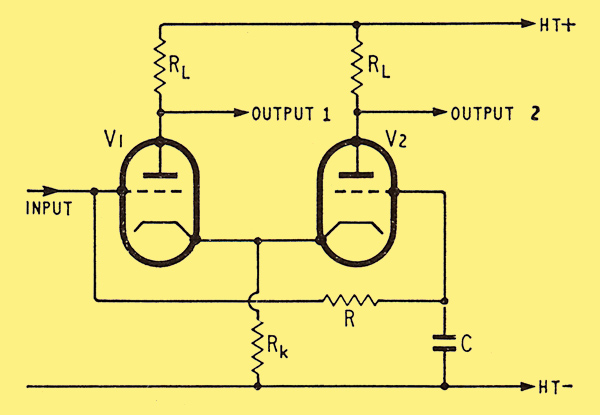
Basic circuit of long-tailed-pair phase-splitter.
Two circuits that suffer from excessive HF phase shift are shown above. The first diagram shows the circuit due to Jeffery [3] Push-Pull Phase-Splitter, E Jeffrey, Wireless World, August 1947, p. 274. and it is unnecessary to go into the details of the phase shift in this circuit again. The interested reader is referred to the correspondence following the publication of a subsequent article [4] Economical High-Gain AF Amplification, Arthur R. Bailey, Wireless World, January 1960, p. 25, (Letters) March, p. 133, April, p. 181, May, p. 244..
The long-tail circuit shown above is well known and widely used but the fact remains that its HF response is relatively poor. This cannot be due to the second half of the valve as this section is effectively driven as a grounded-grid amplifier. The trouble is due to the first half of the valve and is due to that hardy perennial-Miller effect. The gain of this first valve is effectively halved due to the input impedance at the second valve cathode. Even so the Miller capacitance is quite large and certainly cannot be neglected. In order that some estimated value of frequency response can be obtained, some typical values will be taken. Using the ECC83 as a typical valve, the quoted anode-to-grid capacitance is 1.6 pF so the total value will be certainly as large as 2.0 pF when wiring and valve-base capacitances are taken into account. The gain of each half of the valve can be as much as 60 times, but this would be better reduced to a factor of 50 as there is a supply voltage loss in the common-cathode resistor. The overall gain will therefore be about 25 times when used in this phase-splitter. This will give a reflected Miller capacitance of approximately 50 pF, so the total capacitance loading on the previous stage will be about 60 pF if 10 pF is allowed for all other capacitances. With a 100 kΩ source impedance this will give a -3 dB point at about 25 kHz, and this is clearly not good enough when output transformers with primary resonance's of about 150 kHZ are considered. The phase shift of the amplifier circuits must be as small as possible where the output transformer reaches its first primary resonance; and therefore the bandwidth of this type of phase-splitter can easily degrade the total amplifier performance. The use of a step network across the anode load resistor of the driving valve can help in this matter, but only If the step starts well before the natural fall-off frequency of the circuit itself. In the case just considered this would mean starting the fall-off of amplifier gain by the step network at approximately 2.5 kHZ or lower. This would obviously give excessive reduction in loop gain at the high frequencies, with consequent increase in distortion.
The answer therefore lies in producing a fall-off at the HF end of the spectrum that starts at a much higher frequency. This could be attempted by reducing the value of the output impedance of the previous stage. This could be done by negative feedback with consequent gain loss; or alternatively by using a smaller value of anode load resistor. This latter also gives a severe loss in gain, quite apart from the increased noise that is produced by the increased valve current. The answer was therefore seen to lie in producing a phase-splitter that did not give the large input capacitance of the previous circuit.
Circuits are known [5] The New 'Isodyne' Phase-Splitter, E F Worthen, Audio, August 1958, p. 26. that do give good HF response in phase-splitter service, but they suffer from high cost due to the complexity of the circuitry involved. The circuit that was finally evolved (see below) has a cost that is only slightly more than that of the conventional circuit, but has a greatly improved response at high frequencies.
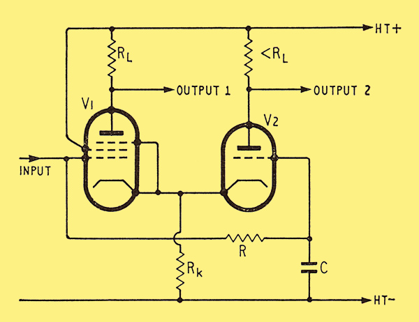
Basic circuit of modified long-tailed-pair phase-splitter.
The operation of the new circuit is just about identical with that of the conventional long-tailed pair except that the first valve is a pentode. This reduces the Miller effect to negligible proportions and increases the total bandwidth by a factor of just under ten times. Even allowing that the gain of the circuit is about 2 dB less than the conventional circuit, this still gives a gain/bandwidth improvement of about seven times. The comparative gain/frequency plots are shown below, where it is seen that the final rate of fall in both cases is identical at 20 dB per decade. This indicates an ultimate phase shift of 90 degrees which was borne out by measurement.
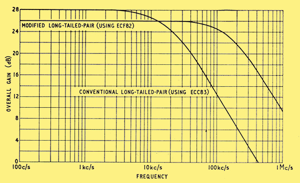
Relative frequency response curves of original and modified long-tailed-pair phase-splitters.
Owing to the partition of valve current in the pentode, the anode load resistor is made somewhat greater than that of the triode stage so that a balanced output is obtained. The circuit can be DC coupled to the previous stage as can the usual one, and a complete 'front-end' for driving the output valves of an amplifier is shown at the top of the article.
This has a built-in 3:1 low-frequency step network that improves LF stability, and a 20:1 HF step network. The HF network may need component values altering for different types of output transformer due to the wide variation in resonant frequencies and other parameters.
This circuit was originally developed for improving the performance of the Radford MAl2 and MA1S amplifiers and certainly did this to great effect. Equally there is no reason why the circuit should not give a considerable improvement in the stability of other amplifiers using good output transformers. The circuit is simple and stable and has no difficulty in providing drive for the largest output valves.
A double-pentode having video amplifier characteristics and low input capacitance would enable greater overall gain to be obtained, but so far the author has not been able to find a valve with suitable characteristics. If such a valve were available, then the overall gain could be increased by a factor of about four times. Where sufficient spare stability margin was available this could lead to a further reduction in the distortion of the amplifier in use.
References
- High Fidelity Sound Engineering, N H Crowhurst (Newnes), p. 130.
- Why do Amplifiers Sound Different, N H Crowhurst, Radio and Television News, March 1957.
- Push-Pull Phase-Splitter, E Jeffrey, Wireless World, August 1947, p. 274.
- Economical High-Gain AF Amplification, Arthur R. Bailey, Wireless World, January 1960, p. 25, (Letters) March, p. 133, April, p. 181, May, p. 244.
- The New 'Isodyne' Phase-Splitter, E F Worthen, Audio, August 1958, p. 26.
|