|
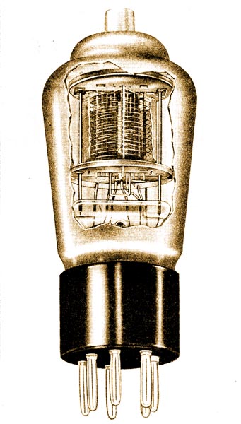
Octode Frequency Changer type FC4
The return to favour of the superheterodyne receiver during recent years is very largely the result of improvements in methods of frequency changing, which have been made possible by the introduction of new and advanced types of valves.
Originally the heterodyning frequency was generated in a separate local oscillator valve, and was super-imposed upon the signal frequency in the so-called 'first detector' or 'mixer' valve.
The next development was the use of a single valve for the dual functions of oscillator and mixer. Successively the double-grid valve, the screened tetrode and the HF pentode were employed in this way and permitted sensible progress to be made. The usual arrangement was to inject the heterodyning frequency by means of a coupling coil in the screen or auxiliary grid circuit.
One of the disadvantages of all such systems was the fact that the re-radiation voltages were somewhat greater than could be considered satisfactory, but substantial improvement in this direction has resulted from the introduction of cathode coupling, whereby the heterodyning frequency is impressed upon the electron stream by means of a very small coupling coil in the cathode lead.
But it was left for the development of the electron-coupled frequency changer to solve the problem of re-radiation. In this system the coupling between the oscillator and the mixer exists within the valve itself, through the medium of the electron stream.
The Mullard Octode
The principle of electron-coupling is seen in its highest form in the Mullard Octode, of which two types are now available:- FC4 for AC mains and FC13 in the Mullard range of Universal (AC/DC) valves.
The Octode, as its name implies, is an 8-electrode valve, having no fewer than six grids and an anode concentrically arranged about a single cathode. The arrangement and functions of the electrodes of a Mullard Octode Frequency Changer are shown below while an internal view of the FC4 is reproduced above.
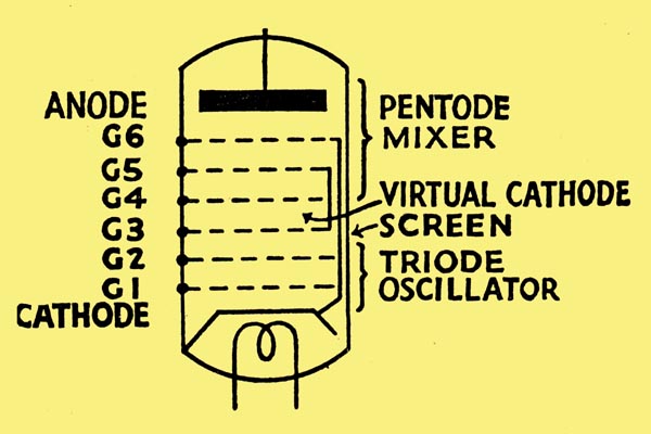
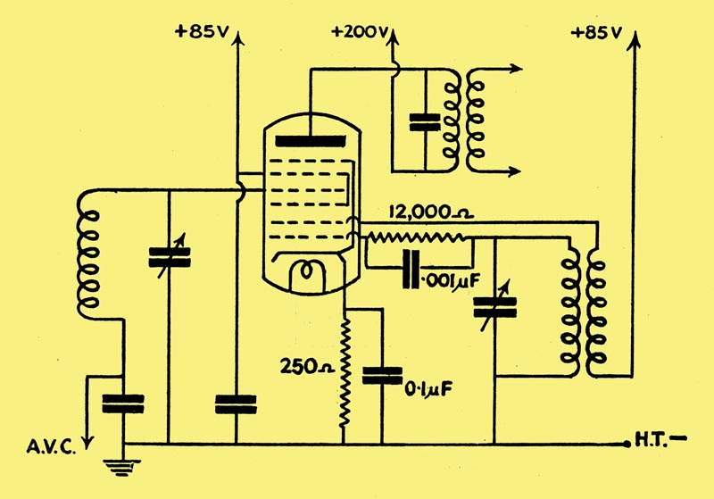
Referring to the Octode diagram it will be seen that the cathode, with Grids 1 and 2, can be considered as a triode, and may be employed for the generation of the heterodyning frequency as indicated in the circuit diagram below.
Owing to the positive potential on the screen (Grid 3), the electron stream will be accelerated and electrons will actually pass into the space between Grids 3 and 4, but by reason of the negative bias applied to the control grid, Grid 4, these electrons will be repulsed, with the result that the region between Grids 3 and 4 will be occupied by a 'space charge' pulsating at heterodyne frequency.
From this 'space charge,' or 'virtual cathode,' .electrons will be drawn by the action of the anode of the octode. It must be understood that this electron stream will oscillate at heterodyne frequency, and with this frequency will be mixed the modulated radio-frequency signal applied to the control grid, Grid 4.
Thus the virtual cathode with Grids 4, 5 and 6 and the anode form a pentode mixer element which is designed to have variable-mu characteristics.
The main advantages of the Mullard Octode Frequency Changer may be summarised as follows:-
(a) Electron coupling minimises re-radiation and simplifies circuit design.
(b) Owing to the separation of the functions of oscillator and mixer, and to the variable-mu characteristics of the valve, AVC can be applied to the mixer as well as to the IF and/or RF stages.
(c) Owing to the pentode characteristic of the mixer, the auxiliary grid voltage is not critical, so that an expensive potentiometer for adjusting this voltage is not required.
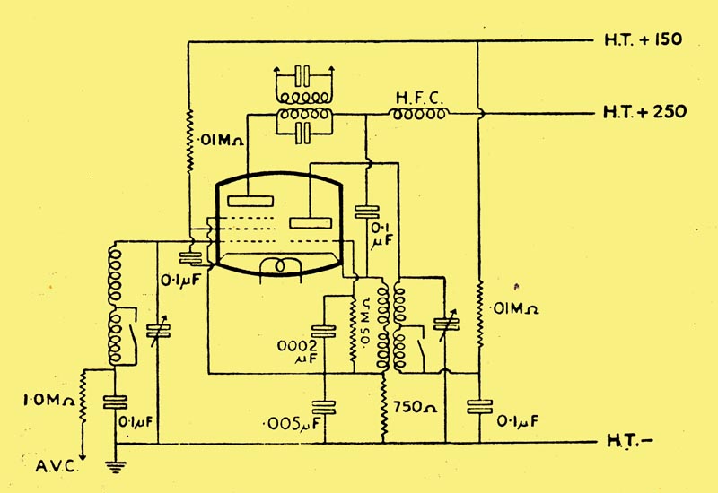
The Mullard Triode-Pentode
Another method of frequency changing favoured by some designers, is by means of a triode-pentode such a the Mullard TP4 for AC mains. This valve comprises a variable-mu HF Pentode mixer element, and a triode oscillator, employing a common cathode but adequately screened from each other.
A practical diagram for the application of the TP4 is shown below from which it will be seen that cathode injection is recommended, and that AVC can be applied to the mixer portion.
The following link leads to a PDF of pages from the original catalogue. FC4 Octode Frequency Changer, FC13 Octode Frequency Changer and TP4 Triode Pentode Frequency Changer.
|