|
This personal account by C H Gardner of Mullard Ltd, was published in 1965 2006. This excellent magazine sadly no longer exists.
Contents
(Within the text click a heading to return here)
Few things have made a greater contribution to the general welfare of mankind than the invention and development of the electronic valve. It is difficult to imagine the chaos that would result in the world if for some reason valves suddenly ceased to operate. Yet it is only sixty years since the very first primitive valves were made, and not a great deal over thirty years since they came into everyday use in their simplest form.
As is the case with many important inventions the birth of the valve was the result of intelligent observation of phenomena not immediately concerned with eventual applications. It occurred when Edison, engaged in work on the development of the electric lamp, realised than an electric current could only be made to pass in one direction between a heated filament and an additional electrode contained in an evacuated bulb. The discovery of a possible application to radio must be credited to Fleming, although he was under the impression that the current was carried by atoms of carbon from the filament. This impression was corrected in 1889 by J J Thomson, who found that the current was due to emission of electrons from the heated filament.
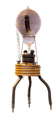
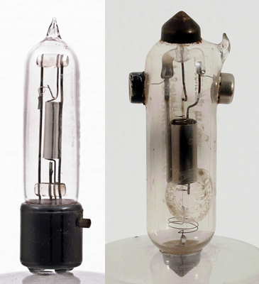
Reproduction Fleming Diode.
Fleming, who had been one of Maxwell's pupils, had been interested in electromagnetic waves ever since the Maxwell Equations had been produced. He duplicated Hertz's experiments of 1887-88. His interest in wireless telegraphy dated from 1896-97 when it became known that Marconi had succeeded in establishing ranges of several miles. Fleming became Scientific Adviser to the Marconi Co in 1899, but continued his duties as a lecturer. (Ambrose Fleming continued to lecture until he was 90 years of age.)
It was not until 1904 that he realised that the electron emission effect could be used as a method of rectifying alternating currents and, as a result, took out a patent to cover the matter. In this patent he describes the construction of a valve with a filament heated by a battery and surrounded by a metal cylinder to which external connection could be made by means of a wire passing through the bulb. His patent covered the use of such a valve as a rectifier. He also mentioned the possibility of producing electrical oscillations by employing two valves working in opposition. It is interesting to note that Wehnelt discovered in the same year that greater emissions could be obtained at a lower temperature by coating the filaments with various oxides.
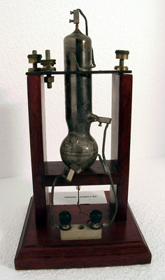
Prototype de Forest Triode.
Two years later Lee de Forest put the third electrode, the grid, in the valve; but it is quite astonishing to find that many further years had to pass before either the two or three electrode valve was adopted to any appreciable extent by the makers of wireless telegraphy equipment.
The reasons for delay were many. With the type of equipment available in the pre-1914 era, sensitivity of the 'detector' was a vital matter. At that time, the Rutherford magnetic detector was in common use. It was a highly reliable but somewhat insensitive piece of equipment, and was gradually being replaced by the crystal detector. The latter varied in sensitivity with the combination of crystals used and, unfortunately, the most sensitive combinations were not the most reliable in service. Nevertheless, even the less sensitive types proved to be more sensitive than the valve rectifiers which were available in that period. Another probable cause of delay was the considerable and lengthy litigation taking place in regard to the validity of some of the patents involved. The Fleming Patent was owned by the Marconi Company and, as the USA courts decided that de Forest could not make triode valves without infringing Marconi patents and that Marconi could not make them without infringing de Forest patents, an impasse was presented that did not resolve itself until well after the termination of the First World War.
It is also true that, in the pre-1914 era, the technique of producing a really hard vacuum in the valve had not been mastered. In fact some of the early rectifiers relied for their operation on the presence of a certain amount of gas which had to be produced by heating an asbestos pellet. When a triode was used for rectification no grid leak was used or was even necessary. The use of a triode as a rectifier came about largely as the result of work carried out by E H Armstrong, who obtained a much harder vacuum for his experimental valves by using methods evolved by Langmuir.
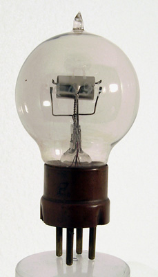
WWI R Type Triode.
In the meantime Round and Franklin had been carrying out experimental which resulted in the discovery of reaction and the use of the valve as an oscillator for heterodyne reception. They also encountered the necessity of reducing the inter-electrode capacitance of the valve in order to obtain effective results from several stages of RF amplification.
Another important aspect was the discovery of the valve's ability to act as a generator of CW oscillations, thus opening the door to radio-telephony, broadcasting, etc. This discovery was made by several people almost simultaneously - Meissner, Armstrong, de Forest, Langmuir, and Round - in 1913. Thus, at the start of the 1914 war, there was a little knowledge of some of the fundamentals of valve design; and the war itself speeded up research work sufficiently to enable a few valves to be produced for service purposes. This resulted in the early production in France of the well known 'French R type' a hard triode valve with a horizontal tungsten filament surrounded by a spiral grid, the whole being enclosed in a cylindrical anode. The connections were brought out to four pins in a moulded base, and the pinning arrangement adopted remained standard for battery triodes for nearly thirty years. The electrode system was held in place by connecting wires which were welded into a glass 'pinch' similar to that used in electric light bulbs. Some work was also done to improve the life of the vacuum in the bulb by degassing the electrodes. This type of valve, with the rather peculiar filament rating of 3.7 Volts, 0.5 Amps, was the first to become available to the amateur at the termination of the war. It appeared in the first place through war disposals and, later, through imports and our own manufacturers.
Due to the intensive experimental work undertaken during the war a great deal more was learnt about the actual working of the valve, together with matters of design and production to improve its performance and life. As a result, it became possible to produce valves with finer tolerances, and to introduce types suitable for specific applications. The technical cynic of today is sometimes apt to suggest that all the valves produced at that time were meant to be identical but that they were sorted out and marked in their various types after test.
An example of the Mullard ORA valve, which appeared on the radio scene in the very early 1920's. The electrode supports are held in the glass 'pinch'.
Be that as it may, the valve had reached the stage of small quantity production and some degree of standardisation. The immense possibilities opened out by its use in wireless communications were becoming apparent. By the early 1920's , manufacturers were able to commence producing simple triodes in much larger quantities than before, and with a reasonable certitude that they would be required as standard equipment in receivers and amplifiers.
The manufacture of such valves required many new types of plant and machinery as numerous new principles were involved. The valve required a much harder vacuum than the electric light bulb, and some method had to be found of retaining the vacuum whilst the valve was in use despite the release of gasses occluded in its various components. Machinery had to be designed for the quantity production of the electrodes, and experiments made in connection with the oxide coating of the filaments.
It was during this period of immense trial and error that broadcasting commenced, with the result that manufacturers were receiving ever-increasing demands necessitating 'mass production' methods. At the same time, technical development was so rapid that any such methods must perforce be of a nature which would enable modifications to be carried out without having to scrap expensive plant.
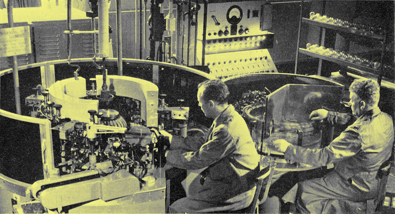
From this time on development progressed along three distinct lines. The need for sensitivity as well as selectivity required research into valves having improved performances. The number of broadcast transmitters and receivers continually increased, necessitating intensive engineering research work into the production of valves in quantities approaching the hundreds of thousands. Thirdly, it was essential to develop and produce more efficient and more reliable valves. To describe in full detail the progression of these lines of research would be impossible in a short series of articles, and those which follow will deal with the major developments that have led to this country alone producing each year more than 60 million valves of an efficiency and reliability undreamt of 40 years ago. In those days it was not unknown for customers to queue up outside the valve factory door to get their share of the day's production of a few dozen valves.
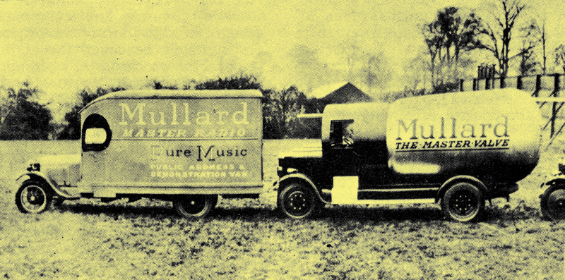
These vans, and particularly that with its bodywork in the shape of a valve of the period, were a familiar sight on the comparatively peaceful roads of 1924 (courtesy of Mullard Ltd.).
From the early 1920's onwards, valve development may be considered as progressing along three distinct but complementary lines. Valves had to have improved performance, intensive engineering research was needed for high quantity production, and valves had to be made more reliable and have longer life.
The valve manufacturer thus found it necessary to establish a number of ancillary departments which included laboratories to meet these research requirements. Further departments were devoted to experimental work connected with valve application and laboratories dealing with the control of quality.
The valve manufacturer had to endeavour to visualise the changes in design which would be necessary to deal with the conditions under which receivers might have to operate several years ahead. Some considerable foresight was necessary here, as a lengthy period between drawing board and production was unavoidable. Normally, a few sample prototypes would be made and tried out in the applications laboratory. If results showed promise a trial run of a few hundred would be made to establish that the type could be manufactured in quantity within the required tolerances, and at a cost which would allow of its adoption within the 'standard' range. Samples would be provided for equipment manufacturers and these would be accompanied by very full reports from the applications laboratory regarding suitable associated circuitry and component design. Modification of the original design might be called for at any stage of the proceedings, whereupon a further journey through the various steps would be needed before quantity production could proceed.
Even apparently minor modifications to a valve are not such a simple matter as may appear at first sight. The valve is a complex device dependent for its successful operation on a number of factors including mechanical construction, electronics and chemistry. A minor change in any single factor may produce unexpected difficulties in one or more of the others. For instance, a change in the metal from which the grid is made could well change the contact potential between cathode and grid, with a consequent alteration in the valves characteristics.
Although quite astonishing performances were being obtained in the early 1920's by the use of simple triode valves as radio frequency amplifiers their limitations were already being recognised. At that time it was quite common to find a combination of five triodes in a broadcast receiver, the first two operating as RF amplifiers, the third as a detector and the final two as audio frequency amplifiers. In many cases the RF valves were coupled by tuned (but not ganged) circuits, stability being obtained at the expense of some loss of amplification. There were also a number of 'suitcase' portable receivers with frame aerials in the lid of the case, and in which all five valves were resistance-capacitance coupled, their function being determined by suitably chosen values of components and the bias applied to the valve grids. One was inclined to a suspicion that, as the batteries ran down, the valves did not always continue to function in the intended manner and, instead of having a 2 RF, detector and 2 AF receiver, one had a detector and 4 AF set.
A major factor influenced the design of receivers of that period and, in fact, continued so to do for some years following. The public were inclined to judge a receiver not upon its quality of reproduction but by the number of stations that it could receive. A further factor in both receiver and valve design was the fact that the filament supply had to be obtained from a heavy accumulator, which had to be carried to the local garage or radio dealer for recharging at all too frequent intervals.
In order to reduce filament consumption, investigation of cathode materials offering adequate emission at lower temperatures was undertaken, and this resulted in the production of what came to be known as 'dull emitter' valves. The filaments of these valves operated at dull red heat instead of with the lamp-like bright glow to which we had been previously accustomed. Dull emitter valves made their debut in the 1924-1926 period, and their ratings varied considerably. One type had a rating of 3 Volts at 0.06 Amps, thus making it suitable for dry battery operation, whilst others were rated at 2 Volts and a higher current.
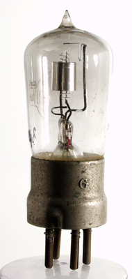
At the same time triode valves of reduced size appeared on the market, these having the curious rating of a quarter of an amp at 1 Volt. This meant that a five valve receiver would consume 1.25 Amps at 1 Volt, a fact which would not indicate a prolonged life for a dry cell. One of these valves, the 'Weco', is shown in the accompanying illustration.
The story of the continual search for cathode materials which could provide both efficiency and long life is one which will be dealt with more fully later.
The world's first screen grid valve.
The inability of the triode valve to provide high amplification of radio frequencies was due to the capacitance between grid and anode causing an undesirable coupling between the input and output circuits. The first tetrode appeared in 1924, the extra grid operating as a screen, but it was appreciably later than 1924 before the screen grid valve began to appear in any quantity in broadcast receivers. It is interesting to note that two well-known home-constructor kits made available by valve manufacturers in 1928, the Mullard 'Master Three' and the Cossor 'Melody Maker', specified battery triodes.
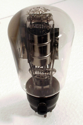
With the appearance of the loud speaker the 'power' valve became available. These 'power' valves were low impedance triodes with longer grid bases and a rather more heavy anode consumption than other valves. A typical 2 volt power valve would have an anode impedance of 2000 Ω, an amplification factor in the region of 7 or 8, and would consume about 10 to 15 mA at 100 or 150 Volts. Being rather expensive so far as HT battery replacement was concerned, they became more popular when the so-called 'battery eliminator' appeared on the scene, as this allowed the HT supply to be obtained from the electric light mains.
A competitor to the 'power' valve arrived in the form of the pentode, this having an extra grid, connected to cathode, between the screening grid and the anode. The extra grid overcame an undesirable feature of the screen grid valve by suppressing secondary emission from the anode.
Pentode valves were designed in two types, one for RF amplification and the other for use as an output valve. The output pentodes had a much shorter grid base than the triode output valves but gave a much higher degree of amplification. The 'quality' enthusiast of that time was apt to suggest that 'quality' could be obtained only by the use of triodes in the output stage, a fact which may come as rather a shock to the user of modern hi-fi equipment. But then there were also those who maintained that real 'quality' could be obtained only from a crystal detector and a pair of headphones and, at a later period, those who affirmed that only a battery set could provide good reception, mains-driven sets being useless for high 'quality'!
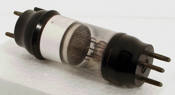
The AC/Pen of 1930 was the first successful indirectly heated audio output valve.
Mention next must be made of the indirectly heated 'all-mains' valves which made their appearance in the 1928-1930 period. In the early versions of these valves the heater was a spiral of wire inserted in an insulating tube which, in turn, was inserted in a nickel cathode tube sprayed with an emissive powder. They were made to operate at 4 volts, 1 amp, the heater supply being taken from a suitable winding on the mains transformer which also provided the necessary HT supply. The rigid cathode made it possible to reduce the clearance between cathode and grid, and thus materially improve the performance of the valve. As the HT supply was also taken from the mains, higher anode currents and voltages could be used. This, in turn, required reconsideration of cathode efficiency in order to obtain the requisite emission without unduly high heater wattage.
Thus, a whole new series of problems arose, a great many of which were concerned with the design of the heater and cathode assembly. The use of indirectly heated valves provided opportunity for numerous developments in circuit design and many such developments, in turn, made more stringent demands on the valves. This is a 'battle' which has carried on for more than 30 years and which still continues. Some of the major difficulties encountered in this battle of progress will now be considered.
In these days of transistors we may be apt to forget that the valve, unlike the semi-conductor, has ‘consumable’ parts which limit its useful life. Such things as broken heaters, insulation breakdown and misplaced electrodes could all cause failure of the valve, but perhaps the greatest problems in practice have been concerned with the life of the cathode. Many of these problems are common to both directly and indirectly heated cathodes, and the latter will be dealt with here in order to illustrate the complexity of the matter. The overcoming of these problems must be considered as a major development in the history of the valve.
An indirectly heated valve employs a heating filament which is insulated from the cathode proper by a coating of, generally, aluminium oxide. The cathode consists of a nickel tube into which the insulated heater is inserted. This nickel tube may be coated with a mixture of strontium and barium carbonates which are converted into oxides whilst the valve is being processed after assembly and when it is being pumped. The gasses released during this chemical change are sucked away by the evacuating pump. The valve is then ‘aged’ by running the heater at a higher than normal temperature with a positive potential applied to the other electrodes. This ‘ageing’ causes a certain percentage of metallic barium and strontium to be formed in the emissive coating and it is the structure of the aged coating, containing atoms of these metals, which provides the effective emissive material. The chemical process is involved, and an important point to note is that, should any oxygen remain in the valve after evacuation or should it be released from the glass or metallic components whilst the valve is in operation, this will re-oxidise the all-important barium and strontium metallic atoms. The result will be a reduction in the emission of the valve.
It will thus be seen that an important stage in valve development was given, firstly, by attaining a very high vacuum and, secondly, by ensuring that this high vacuum would be maintained whilst the valve was in operation.
The ability to obtain and maintain the necessary high vacuum was the result of considerable improvements in the pumping equipment together with the firing of ‘getters’ to remove the last traces of gas as pumping was being completed and just before the valve was being sealed off. Also, the internal components of the valve were raised to a high temperature to drive off any occluded gases, the components being raised to the necessary temperature by eddy currents induced in them from alternating currents of suitable frequency passed through a coil surrounding the bulb. The getter was fired in a similar manner just before the sealing off process took place. Depending upon the processing used, the getter might alternatively be fired as a separate operation after sealing off, with equivalent results. These processes occurred in sequence on a rotating machine, the assembled valve being fed in by an operator and the pumped, gettered and sealed valve being removed on the completion of the cycle.
Various materials have been used for getters, the necessary piece of material being fixed at a suitable point of the assembly. This vital process has many complications, as it is not easy to ensure that the fired getter reaches all the gas molecules or that the final residue is not deposited in undesirable places.
The amount of chemical, physical and engineering research and development necessary to improve the plant and processing in these directions whilst, at the same time, speeding up production may well be imagined. The development has been continuous ever since the 1920’s.
The design and manufacture of the cathode presented many difficulties. A typical example was given by the development of resistance between the nickel tube and the emissive material as the valve was in use, this being often due to minute traces of impurity in the nickel core. The growth of such interface resistance would gradually affect the performance of the valve.
In order to obtain maximum efficiency, the spacing between grid and cathode should be as small as possible. In the very early valves this spacing was quite considerable and, even some 20 years ago, it was usual to find a spacing of a seventh of a millimetre or so. Reduction of this spacing has gradually taken place as the result of improved forms of grid construction and greater rigidity of assembly, and a big step was given by the evolution of a cathode with flat sides and coated with the emissive material by a new method. This provided a hard smooth surface which allowed a cathode-grid spacing of less than a twentieth of a millimetre. The old method of spraying on the emissive material provided a random roughness of such a nature that very fine cathode-grid clearances caused far too great a spread of valve characteristics. The older type of cathode construction sometimes caused cathode material to be carried over to the grid, resulting in this electrode itself emitting. In the case of rectifying valves such material could cause sputtering between cathode and anode, often with dire consequences to associated components.
We cannot leave the subject of the all-important cathode without reference to the heater itself and to the insulation between cathode and heater. There were conflicting requirements for this insulation. Series operation and circuit requirements resulted in many cases, in a considerable difference of potential between cathode and heater. At the same time, good conduction of heat from the heater to the cathode was of importance in order to keep wattage low and heating time within reasonable limits. The insulation had, also, to be of such a nature that it would withstand the heating and cooling of the heater as the set was switched on and off.
Alumina (aluminium oxide) was the material generally used for this insulation. It coated the heater and obviated the earlier arrangement in which the heater was contained in an insulating tube of magnesium oxide. Gradual improvement over a considerable number of years in the technique of coating the heater and in the purity of the alumina has made leakage or breakdown of the cathode heater insulation virtually a thing of the past, in spite of the increased potentials now often present. Heating-up time has also been considerably improved.
Breakdown of the heater itself was a fairly common trouble with the earlier valves. Considerable strain was put on the heater wire by the frequent heating and cooling caused by switching the set on and off. With the reduction in valve size and, consequently, the size of the cathode tube, heater design called for some ingenuity. Basically, the heater consisted of a spiral of wire. Later, the coiled coil heater came into general use, the heater being bent back on itself to form an inverted V. More recently the single wire wire has been replaced by a stranded wire providing greater flexibility. The later constructions have also been effective in the reduction of hum.
Rather a high proportion of space has been devoted to the development of the cathode-heater assembly, but it must be pointed out that without a considerably high performance in this component not only would a reasonable degree of reliability and life for the valve have been unobtainable but the development of the remainder of its assembly would have been impossible.
A major development which has been of general application has been the change in the general assembly towards greater rigidity, reduction in size and improvement in RF performance. At the same time, alteration in construction has required much modification of the manufacturing plant.
The ‘heart’ of the valve, its cathode, was dealt with at some length. The development of this and of the all-glass technique were fundamentals of progress. The all-glass technique is sometimes confused with miniaturisation but this was far from being its main object. As the use of higher and still higher frequencies became a requirement, it was necessary to ensure that the self capacitance, the inductance, and the dielectric losses in the valve were all reduced to a minimum. In order to increase the efficiency of the valve and reduce the spread of characteristics in production it became necessary to devise a more rigid form of construction.
The peanut Wecovalve & Marconi V24
Although a form of all-glass construction had been used in the very early days, examples being the ‘peanut’ valve and the Marconi ‘V’ series, these forms of assembly were unsuitable for mains valves and did not lend themselves to mass production methods. It was in 1938 that the pressed glass base came into use and this did away with the pinch type of construction with its many disadvantages.
The basic idea behind the glass base construction was to seal the connecting pins into a glass disc. The top ends of the pins were connected to the electrodes, the lower ends being intended for insertion into a valveholder of advanced design. These valves had either 8 or 9 pins as standard. Various ideas were used in order to ease the location of the valve in its holder. In some receivers, and especially in TV sets, some of the valves were located in positions which required the use of such accessories as dental mirrors to locate to locate the 8 or 9 pins in their respective sockets. Some of the early valves were fitted round the base with a metal rim having a projection on the side, the associated valveholder being surmounted with a metal skirt having a vertical groove to take the projection. When the projection on the valve was slid down the groove the pins were in the right position to enter the holes in the socket.
Later, the metal rim and projection were replaced by a pip formed on the glass valve base itself and, finally, both of these locating devices were dispensed with, correct insertion in the valveholder being governed by the spacing of the pins.
This final construction was not too popular with the service engineer as valves still continued to be placed in TV receivers in positions where it was almost impossible to see the holes in the valve socket. This difficulty also caused another headache for the valve manufacturer. Owing to the difficulty of getting at some of these valves they were apt to be withdrawn from their holders at an angle. This put a strain on the pins and, consequently, a strain on the glass base. Minute cracks in the glass then became possible, causing a loss of vacuum and failure of the valve. The use of a softer metal for the pins was apt to result in their being bent during valve withdrawal, but straightening jigs became available for the service engineer.
As the valve pins were moulded directly into the glass base it was essential that the pins and glass should have similar coefficients of expansion. The necessary type of glass was unsuitable for the envelope and, to avoid undesirable strains being set up as the valve heated and cooled, the base had to be built up in the form of a sandwich of different types of glass. This allowed low temperature sealing of the bulb to the base and avoided any oxidisation of the electrodes or poisoning of the cathode due to the heat of sealing. These are very important matters now that the electrode system has been brought as close as possible to the base in order to reduce the self-inductance of the pins at the ultra-high frequencies currently in use.
Much could be written about the glass techniques used in valve manufacture, and the research work carried out in order to obtain the various types of glass required. For instance, although certain types of glass are entirely suitable for the various processes, they are subject to electrolysis when the valve is in use and can result in the appearance of conductive deposits between the electrodes. But sufficient may have been said to show that glass techniques, vacuum techniques, and the construction of the cathode have been basic matters in valve development. Without success in these developments the work done on electrode geometry would have been to no avail.
With the rapid development of electronics the number of applications for valves extended well beyond the confines of communication and entertainment. Some of these applications called for a very high degree of reliability, often under very arduous conditions where valve failure might not only be costly but very dangerous.
In almost every manufactured article there is a ‘built in’ reliability and ‘lasting power’ which is reflected in the price. One might almost state that ‘perfection’ is unattainable. ‘Near perfection’ is possible but can be very costly. ‘Reasonable perfection’ at reasonable cost is the aim of the manufacturer of the good class product and, to attain and maintain this, an efficient quality control organisation is essential. Particularly is this the case with a product such as the valve in which complicated chemical electrical and mechanical matters in manufacture and use will effect its reliability and endurance.
When an application demands maximum reliability regardless of cost, the investigations and experience incurred in achieving this will usually allow many of the features involved being adopted in later manufacture of the ‘standard’ product; and this factor has been very true in the case of the valve. Manufacturers’ quality control departments soon realised that a certain proportion of the production failed factory tests. Of those that passed these exacting tests, another proportion failed during early life in the field. A high proportion still remained and the failure rate over a long period was very low until an ‘end of life’ time was reached at which all the remainder had arrived at a stage where they were ‘worn out’.
It was therefore necessary to carry out investigations to discover the reason for the failure of a small proportion of valves which had satisfactorily passed the rigid factory tests but which still failed at an early period in use. In some cases certain applications accentuated the early failures. In others no such relationship was traceable and the faults were of a more random nature.
Failure of a valve in entertainment equipment has a nuisance value only, but failure of a valve used, for instance, in aircraft communication or control might present disastrous possibilities. Failure of valves used in repeaters in cables buried under the ocean or valves used in the automatic control of intricate machinery might entail enormously expensive results, but if such early random failures could be overcome and the ‘end of life’ time of the remainder were known, a position could be arrived at which would allow replacement before failure occurred.
One hundred percent reliability is virtually unattainable although it can be very nearly reached. In modern installations where an extremely high degree of safety is required it is usual to duplicate or triplicate equipment, with automatic switch-over arrangements if failure takes place. As there are many components other than valves which are equally, if not more, subject to random failure, an arrangement of this nature guards against the failure of such components as well.
The causes of early random failures are somewhat complex, but two of the more obvious ones may be quoted as examples. Equipment used for certain applications, such as in military vehicles or aircraft, or for the control of vibrating machinery, can be subject to intense vibration. In some cases this has been found to be severe enough to cause serious displacement of the valve electrodes, vibration of the electrode supports having caused gradual elongation of the holes in the supporting micas. The ‘cure’ came about by the shortening of the electrode system and the use of materials providing greater rigidity.
Other random failures proved to be due to microscopic impurities getting into the valve during assembly or during the manufacture of the grids. Such impurities might lie dormant in a position in the assembly where they cause no harm, only to later find their way into a position which might cause inter-electrode short-circuits or leakages. This resulted in the modern method of ‘dust free’ manufacture in which the valves are assembled by operatives in special clothing and in sections of the factory where precautions are taken to exclude any form of dust. Grids are now manufactured without ever being touched by the human hand and, as a further precaution, the long lengths of grid assemblies are contained in protective tubes.
From time to time particular applications have resulted in the appearance of conditions which were not apparent in the valve when employed for its original design application. In many cases these conditions became apparent only after the valves have been in service for some time. Technical collaboration between equipment designers and the valve manufacturer is close and constant but, nevertheless, difficulties of this nature still appear on occasions. When they do, speed in correcting the matter is of prime importance. Usually the trouble can be overcome by minor valve or circuit modifications, but what might appear to be a minor modification of a valve might present unusual difficulties. As we have already seen, the use of different material for the control grid might materially alter the characteristics of the valve, because of the change in contact potential.
The development of the valve from the early battery triode to its present high state of efficiency and reliability is a fascinating story of endeavour, ingenuity in research work, and the practical application of many sciences. In the early stages of development it was often possible to attribute progress to individuals, but the situation soon arose in which advances were the result of team work amongst scientists, chemists, and engineers.
Today, one thinks of production in terms approaching the hundreds of millions. In a rapidly expanding industry such as we have in electronics, new applications, new requirements and new facets of knowledge are almost hourly occurrences. Sometimes there is a tendency to think of the valve as ‘outdated’ and replaced by the semiconductor. It is as well to realise that the two are complementary and that further research and development of the valve continues, and is likely to do so for many more years to come.
C H Gardner
|