|
Among the many kinds of electronic devices made by Mullard are two small groups known as Voltage Stabilisers and Voltage Reference Tubes. They are not valves in the familiar sense: they do not detect, they do not amplify. Their job is to maintain steady DC voltages, either in power supplies where mains variation or changing load would otherwise produce unwanted voltage changes, or in circuits in which a reliable standard voltage is required.
Voltage Stabilisers
The simplest and most usual form of electronic stabiliser consists of two metal electrodes: the anode, which is usually a small rod, and the cathode, which is a relatively large plate or cylinder. There is no heater or filament, therefore the stabiliser is a 'cold-cathode tube. The electrodes are mounted in a glass bulb which contains one or more of the rare gases (neon, argon, helium, etc.), at low pressure.
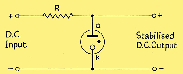
Fig. 1. Simple Stabiliser Circuit.
When a suitable DC potential is applied, in the manner shown in Fig. 1, a current flows through the tube, a glow appears at the cathode, and a voltage (known as the tube drop or burning voltage) is set up between anode and cathode (a and k in Fig. 1). This voltage has the useful property of being almost unaffected by changes in the current flowing through the tube. Thus, if the voltages obtained at various currents are plotted, the resulting graph is of the form shown in Fig. 2.
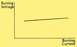
Fig. 2. Typical stabiliser characteristics.
This flat characteristic has two effects in the circuit of Fig. 1. If the input voltage changes, the current through the tube and the resistance R will also change; but, as Fig. 2 shows, the voltage across the tube will remain the same. Thus the voltage change occurs only across the resistance R; it is not passed on to the output terminals. On the other hand, if the load across the output draws a varying current, the current through the tube will vary also; but, again, the burning voltage, and therefore the output voltage, will remain steady. Thus, within the ratings of the tube, the output voltage is not affected by variations of either the supply or the load. In practice the voltage-current characteristic of the tube is not quite flat. There is a small rise in voltage as the current is increased. The voltage difference which exists between the extremities of current range of any tube is known as the 'regulation' of the tube. Ideally it should be zero.
The published current limits of a stabiliser should be strictly observed. If high loads reduce the tube current below a certain value, the glow will go out. Conversely, if the maximum permissible tube current is exceeded when the load current falls, the tube may be rapidly damaged. The available output current is equal to the difference between the maximum and minimum current limits of the tube.
The voltage of any particular stabiliser is determined largely by the metal and gas which are used. As there are few suitable metals and fewer gases, the number of possible operating voltages is limited. There is, however, a useful range of tubes which stabilise at voltages between 80 V and 150 V. Higher voltages can be obtained by series connection.
The supply voltage must be high enough to start the glow discharge, the necessary value being usually greater than the operating voltages. Stabilisers should not be reversed: the anode should always be more positive than the cathode.
Voltage Reference Tubes
It is often necessary to have a fixed reference voltage in a circuit. Standard cells have many disadvantages: their voltages are inconveniently low, their current limitations are severe, and they are very sensitive to temperature changes and to physical movement. Certain types of stabiliser, notably those using the Mullard sputter technique. have been designed to give exceptionally constant operating voltages during very long periods of use or storage. Such tubes are fed from supplies which have already been stabilised in the way described above thus they operate not with a varying current but at one fixed value (say halfway along the curve in Fig. 2. Under these conditions, the output voltage remains constant, for short or long periods, within a fraction of one per cent.
The following table gives the main characteristics of the Mullard range of stabilisers and reference tubes.
Type
|
Description
| Starting
Voltage
(V) | Burning
Voltage
(V) | Min
Current
(mA) | Max
Current
(mA) |
Base
| | Voltage Reference | 125 | 83 - 86 | 1.0 | 8.0 | | | Voltage Reference | 125 | 83 - 87 | 1.0 | 10.0 | | | Stabiliser | 125 | 86 - 94 | 1.0 | 40.0 | | | Stabiliser | 180 | 146 - 154 | 5.0 | 15.0 | |
|