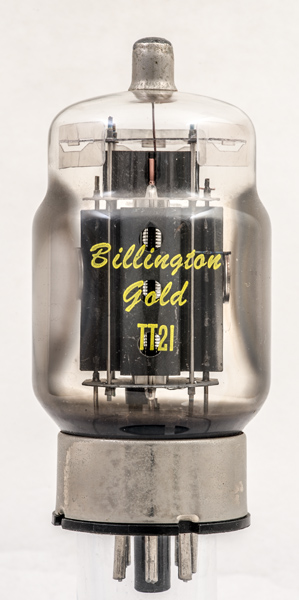
The TT21 and TT22 differ only in heater voltage. The TT21 is for 6.3 Volt use and the TT22 has a 12.6 Volt heater and was aimed at mobile transmitters. Both valves are electrically identical and aimed at the SSB transmitter market. Both are also rated for Class C use as well as for the linear amplifiers required for Single Sideband transmission.
Maximum power output of 146 Watts comes in the efficient Class C mode, SSB will produce 110 Watts and as a Class AB1 audio amplifier some 50 Watts are possible or 100 Watts with fixed bias. The data-sheet says that the TT21/22 may be used, as a pair, in place of the KT88 for audio use. This is not a revelation as the two Types have the same design history, the TT21/22 being modified for higher peak anode voltages and having a top cap anode connection to prevent flash-over at the base but otherwise the same valve.
In an earlier generation of valves the landmark 6L6G had a transmitting version also - the 807 - again with a top cap for higher anode voltages. In both cases the anode dissipation remains the same and so it would be wrong to think that the TT21/2 could be used at audio for greater power than the KT88.
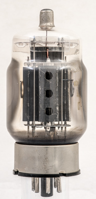
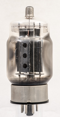
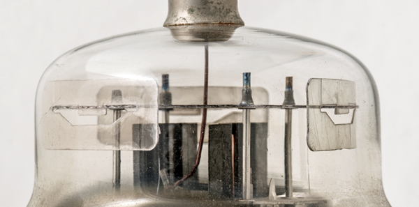
Looking along the axis of the grids that pass flat across the cathode and appear to be aligned with identical pitch. The getter holders are placed either side of the side flanges that provide extra surface area for cooling by radiation and are sited at the points of maximum heat production where the high speed electrons hit the anode. The control grid has a pair of large heat radiating fins attached to the tops of the copper supports.
Between the anode and the lower mica can be seen the bright beam plate that repels secondary electrons.
The top of the envelope showing the anode connection and grid cooling fins.
The wide glass tube envelope is 52 mm in diameter, and excluding the IO base pins is 104 mm tall.
References: Data-sheet. Type TT21 was first introduced in 1961. See also1961 adverts.